FreesScPaI RlEeGISSTMeERCmS33Di3cE8S9oCRnIPdTuIOcNtor, Inc.
Table 49.
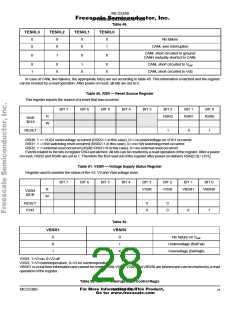
TESRL3
TESRL2
TESRL1
TESRL0
0
0
0
0
0
0
1
No failure
X
CANL wire interruption
CANL short circuited to ground/
CANH mutually shorted to CANL
0
1
0
X
X
1
X
X
1
0
X
X
CANL short circuited to Vbat
CANL short circuited to Vdd
In case of CANL line failures, the appropriate bit(s) are set according to table 48. This information is latched and the register
can be reseted by a read operation. After power on reset, all bits are set to 0.
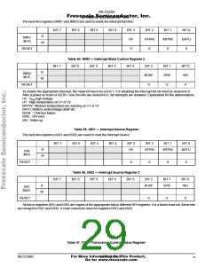
Table 50. RSR — Reset Source Register
This register reports the source of a reset that has occurred
.
BIT 7
BIT 6
BIT 5
BIT 4
BIT 3
BIT 2
BIT 1
BIT 0
R
RSR2
RSR1
RSR0
RSR
$018
W
RESET
1
0
1
RSR0: 1 => VDD1 undervoltage occurred (RSR2=1 in this case), 0=> no undervoltage on VDD1 occurred
RSR1: 1 =>SW watchdog reset occurred (RSR2=1 in this case), 0=>no SW watchdog reset occurred
RSR2: 1 =>external reset occurred (RSR0=RSR1=0 in this case), 0=>no external reset occurred
Events related to the bits in register RSR are latched. All bits can be reseted by a read operation of the register. After a power
on reset, RSR2 and RSR0 are set to 1. Therefore the first read out of the register after power on delivers RSR[2:0] = [101].
Table 51. VSSR — Voltage Supply Status Register
Register used to monitor the status of the V2, V3 and Vbat voltage level.
BIT 7
BIT 6
BIT 5
BIT 4
BIT 3
V3SR
BIT 2
V2SR
BIT 1
BIT 0
R
VBSR1
VBSR0
VSSR
$01B
W
RESET
POR
0
0
0
0
0
1
Table 52.
VBSR1
VBSR0
0
X
1
0
1
No failure on Vbat
Undervoltage (BatFail)
Overvoltage (BatHigh)
X
V2SR: 1=V2 on, 0=V2 off
V3SR: 1=V3 overtemperature, 0=V3 no overtemperature
VBSR1 is a real time information and cannot be reseted. Bits V3SR, V2SR and VBSR0 are latched and can be reseted by a read
operation of the register.
Table 53. IMR1 — Interrupt Mask Control Regis
For More Information On This Product,
MC33389
MOTOROLA
28
Go to: www.freescale.com

 MOTOROLA [ MOTOROLA ]