FreesScPaI RlEeGISSTMeERCmS33Di3cE8S9oCRnIPdTuIOcNtor, Inc.
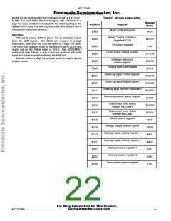
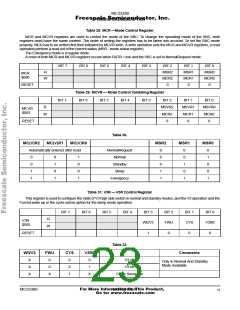
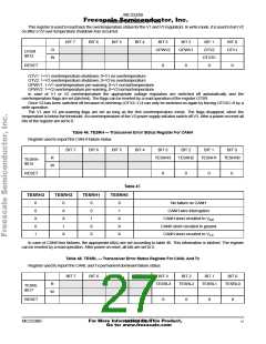
Table 28. MCR —Mode Control Register
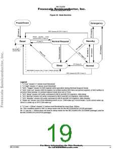
MCR and MCVR registers are used to control the mode of the SBC. To change the operating mode of the SBC, both
registers must have the same content. The order of writing the registers has to be taken into account. To set the SBC mode
properly, MCR has to be written first then followed by MCVR write. A write operation sets the MCR and MCVR registers, a read
operation perform a read out of the current status (MSR - mode status register).
The Emergency mode is a regular mode.
A reset of both MCR and MCVR registers occurs when RSTB = low and the SBC is set to NormalRequest mode.
BIT 7
BIT 6
BIT 5
BIT 4
BIT 3
BIT 2
MSR2
MCR2
0
BIT 1
MSR1
MCR1
0
BIT 0
MSR0
MCR0
0
R
MCR
$000
W
RESET
Table 29. MCVR — Mode Control Validating Register
BIT 7
BIT 6
BIT 5
BIT 4
BIT 3
BIT 2
MSVR2
MCR2
0
BIT 1
MSVR1
MCR1
0
BIT 0
MSVR0
MCR0
0
R
MCVR
$003
W
RESET
Table 30.
MC(V)R2
MC(V)R1
MC(V)R0
MSR2
MSR1
MSR0
Automatically entered after reset
NormalRequest
Normal
0
0
0
1
1
0
0
1
0
1
0
1
0
0
1
0
0
1
1
0
1
0
1
1
0
0
1
Standby
Sleep
Emergency
Table 31. V3R — V3R Control Register
This register is used to configure the state of V3 high side switch in normal and standby modes, and the V3 operation and the
Forced wake up or the cyclic sense option for the sleep mode operation.
BIT 7
BIT 6
BIT 5
BIT 4
BIT 3
WI2V3
1
BIT 2
FWU
0
BIT 1
CYS
0
BIT 0
V3R0
0
R
V3R
$005
W
RESET
Table 32.
WI2V3
FWU
CYS
V3R0
Comments
X
X
X
0
0
X
0
0
1
0
1
V3 off
V3 on
Only In Normal And Standby
Mode Available
X
Cyclic Sense On
For More Information On This Product,
MC33389
MOTOROLA
23
Go to: www.freescale.com

 MOTOROLA [ MOTOROLA ]