MT9092
Receive Byte Status
in Table 2. Note that the FIFO filling threshold, where
an interrupt (RxFf if unmasked) will occur, can be set
to a high level 15 (default) or to a low level 5 by the
Flrx bit in the HDLC Control Register 2 (address
05h).
As each received packet byte is written into the Rx
FIFO two bits are appended to indicate the status of
that byte. As these bytes are read from the Rx FIFO
the status bits are made available to the
microprocessor in the HDLC Status Register
(address 04h) as RxBS1 and RxBS2. Since the
information contained in RxBS1 & RxBS2 pertains to
the byte about to be read from the Rx FIFO, it is
important that this information be read before
reading the data byte from the FIFO. RxBS1 and
RxBS2 are encoded as shown in Table 2. A good
packet indication means a good FCS and no frame
abort whereas a bad packet indication means either
an incorrect FCS or a frame abort occurred.
In the case of an Rx FIFO overflow, an attempt by
the receiver to write data into an already full FIFO,
the receiver is disabled causing it to stop writing to
the Rx FIFO. The remainder of the current receive
packet is therefore ignored. The receiver will be re-
enabled when the next flag is detected but will
overflow again if the Rx FIFO level has not been
reduced to less than full. If two 'first byte' (RxBS1
and RxBS2) conditions are observed in the FIFO
without an intervening 'last byte' then an overflow
occurred for the first packet.
Receive FIFO Status
Receive Interrupts
The receive FIFO is 19 bytes deep (address 02h). As
data is loaded into (from the serial port) and
extracted from (via the microport) the Rx FIFO the
present 'fill state' can be monitored using the Rxstat1
and Rxstat2 bits found in the HDLC Status Register
(address 04h). These states are encoded as shown
The HDLC Interrupt Enable Register (address 06h)
is used to select (unmask) only those interrupts
which are deemed important to the microprocessor.
After a PWRST or software RST all enable bits will
be cleared causing all interrupts to be masked.
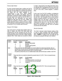
RxBS2,
RxBS1
Are status bits from the Rx FIFO.
RxBS2
RxBS1
Byte status
1
0
1
0
1
1
0
0
last byte (bad packet)
first byte
last byte (good packet)
packet byte
Note
-
If two consecutive first byte signals are received without an intervening last byte, then an
overflow has occurred and the first packet (or packets) are bad. A bad packet indicates that
either a frame abort had occurred or the FCS did not match.
-
On power-up these bits are in an indeterminate state until the first byte is written to Rx FIFO.
Txstat2,
Txstat1
These two bits are encoded to indicate the present state of Tx FIFO. This is an asynchronous
event.
Txstat2
Txstat1
Tx FIFO Status
0
0
1
1
0
1
1
0
TxFULL
5 OR MORE BYTES (15 if Fltx set)
4 OR LESS BYTES (14 if Fltx set)
TxEMPTY
Rxstat2,
Rxstat1
These two bits are encoded to indicate the present state of Rx FIFO. This is an asynchronous
event.
Rxstat2
Rxstat1
Rx FIFO Status
0
0
1
1
0
1
1
0
RxEMPTY
14 OR LESS BYTES (4 if Flrx set)
15 OR MORE BYTES (5 if Flrx set)
RxOVERFLOW EXISTS
Table 2 - HDLC Status Bits
7-15

 MITEL [ MITEL NETWORKS CORPORATION ]