Advanced Information
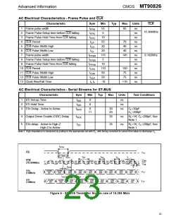
CMOS MT90826
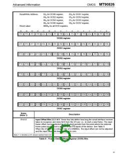
15
14
13
12
11
10
9
8
7
6
5
4
3
2
1
0
CAB
6
SAB
3
SAB
4
SAB
2
SAB
1
SAB
0
CAB
7
CAB CAB CAB CAB CAB CAB
TM1 TM0
OE
5
4
3
2
1
0
Bit
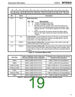
15-14
Name
Description
TM1-0
Mode Select Bits.
TM1 TM0
Mode Selection
0
1
0
0
0
1
Variable Throughput Delay mode
Constant Throughput Delay mode
Message mode; the contents of the connection memory are
output on the corresponding output channel and stream. Only
the lower byte (bit 7 - bit 0) will be output to the ST-BUS output
pins.
1
1
Bit Error Test mode; the pseudo random test pattern will be
output on the output channel and stream associated with this
location.
13
OE
Output Enable. This bit enables the drivers of STo pins on a per-channel
basis. When 1, the STo output driver functions normally. When 0, the STo
output driver is in a high-impedance state.
12-8
7-0
SAB4-0
CAB7-0
Source Stream Address Bits. The binary value is the number of the data
stream for the source of the connection.
Source Channel Address Bits. The binary value is the number of the channel
for the source of the connection. When the message mode is enabled, these
entire 8 bits are output on the output channel and stream associated with this
location.
Table 14 - Connection Memory Bits
SAB4 to SAB0 Bits Used to Determine
the Source Stream of the connection
CAB Bits Used to Determine the Source
Channel of the Connection
Data Rate
8 Mb/s
16Mb/s
SAB4 to SAB0 (STi0 to STi31)
SAB3 to SAB0 (STi0 to STi15)
SAB4 to SAB0 (STi0 to STi31)
SAB3 to SAB0 (STi0 to STi19)
SAB4 to SAB0 (STi0 to STi31)
SAB4 to SAB0 (STi0 to STi31)
SAB4 to SAB0 (STi0 to STi31)
CAB6 to CAB0 (128 channel/frame)
CAB7 to CAB0 (256 channel/frame)
CAB6 to CAB0 (64 or 128 channel/frame)
CAB7 to CAB0 (128 or 256 channel/frame)
CAB5 to CAB0 (64 channel/frame)
4 Mb/s & 8 Mb/s
16 Mb/s & 8 Mb/s
4 Mb/s
2 Mb/s & 4 Mb/s
2 Mb/s
CAB5 to CAB0 (32 or 64 channel/frame)
CAB4 to CAB0 (32 channel/frame)
Table 15 - SAB and CAB Bits Programming for various interface mode
19

 MITEL [ MITEL NETWORKS CORPORATION ]