MT90826 CMOS
Advanced Information
Absolute Maximum Ratings*
Parameter
Symbol
Min
Max
Units
1
2
Supply Voltage
V
-0.3
5.0
V
V
DD
Voltage on any 3.3V tolerant pin I/O (other than sup-
ply pins)
V
VSS - 0.3
V
+ 0.3
DD
I
3
Voltage on any 5V tolerant pin I/O (other than sup-
ply pins)
V
VSS - 0.3
5.0
V
I
4
5
6
Continuous Current at digital outputs
Package power dissipation
Storage temperature
I
20
1
mA
W
o
P
T
D
- 65
+125
°C
S
* Exceeding these values may cause permanent damage. Functional operation under these conditions is not implied
.
Recommended Operating Conditions - Voltages are with respect to ground (V ) unless otherwise stated.
ss
Characteristics
Operating Temperature
Sym
Min
Typ
Max
Units Test Conditions
1
2
3
4
5
TOP
VDD
VIH
VIH
VIL
-40
3.0
+85
3.6
°C
V
Positive Supply
Input High Voltage
0.7VDD
VDD
V
Input High Voltage on 5V Tolerant Inputs
Input Low Voltage
5.5
V
VSS
0.3VDD
V
DC Electrical Characteristics - Voltages are with respect to ground (V ) unless otherwise stated.
ss
Characteristics
Supply Current
Sym
Min
Typ
Max
Units
Test Conditions
1
2
3
4
I
64
100
mA Output unloaded
DD
Input High Voltage
Input Low Voltage
V
0.7VDD
V
V
IH
I
N
P
U
T
S
V
0.3VDD
IL
Input Leakage (input pins)
Input Leakage (with pull-up
or pull-down)
I
15
50
µA
µA
IL
I
0≤<V≤V
See Note 1
DD
BL
5
6
7
8
Input Pin Capacitance
Output High Voltage
C
10
pF
V
I
O
U
T
P
U
T
V
0.8VDD
I
I
= 10mA
= 10mA
OH
OH
OL
Output Low Voltage
V
0.4
5
V
OL
OZ
High Impedance Leakage
Output Pin Capacitance
I
µA
pF
0 < V < V
See Note 1
DD
S
9
C
10
O
Note:
1. Maximum leakage on pins (output or I/O pins in high impedance state) is over an applied voltage (V)
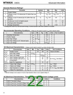
AC Electrical Characteristics - Timing Parameter Measurement Voltage Levels
Characteristics
Sym
Level
Units
Conditions
1
2
3
CMOS Threshold Voltage
V
0.5VDD
0.7VDD
0.3VDD
V
V
V
TT
CMOS Rise/Fall Threshold Voltage High
CMOS Rise/Fall Threshold Voltage Low
V
HM
V
LM
22

 MITEL [ MITEL NETWORKS CORPORATION ]