MT90826 CMOS
Advanced Information
•
Test Reset (TRST)
Resets the JTAG scan structure. This pin is
internally pulled to VDD.
JTAG Support
The MT90826 JTAG interface conforms to the
Boundary-Scan standard IEEE1149.1. This standard
specifies a design-for-testability technique called
Boundary-Scan test (BST). The operation of the
boundary-scan circuitry is controlled by an external
test access port (TAP) Controller.
Instruction Register
In accordance with the IEEE 1149.1 standard, the
MT90863 uses public instructions. The JTAG
Interface contains a two-bit instruction register.
Instructions are serially loaded into the instruction
register from the TDI when the TAP Controller is in
its shifted-IR state. Subsequently, the instructions
are decoded to achieve two basic functions: to select
the test data register that may operate while the
instruction is current, and to define the serial test
data register path, which is used to shift data
between TDI and DO during data register scanning.
Test Access Port (TAP)
The Test Access Port (TAP) provides access to the
many test functions of the MT90826. It consists of
three input pins and one output pin. The following
pins are from the TAP.
•
Test Clock Input (TCK)
TCK provides the clock for the test logic. The
TCK does not interfere with any on-chip clock
and thus remain independent. The TCK permits
shifting of test data into or out of the Boundary-
Scan register cells concurrently with the
operation of the device and without interfering
with the on-chip logic.
Test Data Register
As specified in IEEE 1149.1, the MT90826 JTAG
Interface contains three test data registers:
•
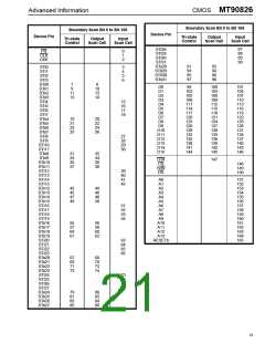
The Boundary-Scan register
The Boundary-Scan register consists of a
series of Boundary-Scan cells arranged to form
a scan path around the boundary of the
MT90863 core logic.
•
Test Mode Select Input (TMS)
The logic signals received at the TMS input are
interpreted by the TAP Controller to control the
test operations. The TMS signals are sampled
at the rising edge of the TCK pulse. This pin is
internally pulled to Vdd when it is not driven
from an external source.
•
•
The Bypass Register
The Bypass register is a single stage shift
register that provides a one-bit path from TDI to
its TDO.
•
Test Data Input (TDI)
The Device Identification Register
Serial input data applied to this port is fed
either into the instruction register or into a test
data register, depending on the sequence
previously applied to the TMS input. Both
registers are described in a subsequent
section. The received input data is sampled at
the rising edge of TCK pulses. This pin is
internally pulled to Vdd when it is not driven
from an external source.
The device identification register is a 32-bit
register with the register contain of:
MSB
LSB
0000 0000 1000 0010 0110 0001 0100 1011
The LSB bit in the device identification register is
the first bit clock out.
•
Test Data Output (TDO)
The MT90826 scan register contains 165 bits.
Depending on the sequence previously applied
to the TMS input, the contents of either the
instruction register or data register are serially
shifted out towards the TDO. The data out of
the TDO is clocked on the falling edge of the
TCK pulses. When no data is shifted through
the boundary scan cells, the TDO driver is set
to a high impedance state.
20

 MITEL [ MITEL NETWORKS CORPORATION ]