MT9079
1) by programming the SOFF7-0 bits to select the
desired throughput delay, which is indicated by
the phase status word bits RxTS4-0 and
RxBC2-0.
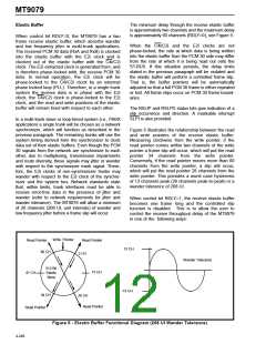
The MT9079 framing algorithm supports automatic
interworking of interfaces with and without CRC-4
processing capabilities. That is, if an interface with
CRC-4 capability, achieves valid basic frame
alignment, but does not achieve CRC-4 multiframe
alignment by the end of a predefined period, the
distant end is considered to be a non-CRC-4
interface. When the distant end is a non-CRC-4
interface, the near end automatically suspends
receive CRC-4 functions, continues to transmit
CRC-4 data to the distant end with its E-bits set to
zero, and provides a status indication. Naturally, if
2) by controlling the position of the F0i pulse with
respect to the received time slot zero position.
The phase status word bits RxTS4-0 and
RxBC2-0 will also indicate the delay in this
application.
With RDLY=1, the elastic buffer may underflow or
overflow. This is indicated by the RSLIP and RSLPD
status bits. If RSLPD=0, the elastic buffer has
overflowed and a bit was lost; if RSLPD=1, a
the
distant
end
initially
achieves
CRC-4
synchronization, CRC-4 processing will be carried
out by both ends. This feature is selected when
control bit AUTC = 0. See Figure 6 for more details.
underflow condition occurred and
repeated.
a
bit was
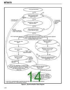
Notes for Figure 6:
Framing Algorithm
1) The basic frame alignment, signalling multiframe
alignment, and CRC-4 multiframe alignment
functions operate in parallel and are independent.
The
MT9079
contains
framing
three
algorithms.
distinct,
but
These
interdependent,
algorithms are for basic frame alignment, signalling
multiframe alignment and CRC-4 multiframe
alignment. Figure 6 is a state diagram that illustrates
these functions and how they interact.
2) The receive channel associated signalling bits
and signalling multiframe alignment bit will be frozen
when multiframe alignment is lost.
3) Manual re-framing of the receive basic frame
alignment and signalling multiframe alignment
functions can be performed at any time.
After power-up the basic frame alignment framer will
search for a frame alignment signal (FAS) in the
PCM 30 receive bit stream. Once the FAS is
detected, the corresponding bit two of the non-frame
alignment signal (NFAS) is checked. If bit two of the
NFAS is zero a new search for basic frame alignment
is initiated. If bit two of the NFAS is one and the next
FAS is correct, the algorithm declares that basic
frame synchronization has been found (i.e., SYNC is
low).
4) The transmit RAI bit will be one until basic frame
alignment is established, then it will be zero.
5) E-bits can be optionally set to zero until the
equipment interworking relationship is established.
When this has been determined one of the following
will take place:
Once basic frame alignment is acquired the
signalling and CRC-4 multiframe searches will be
initiated. The signalling multiframe algorithm will
align to the first multiframe alignment signal pattern
(MFAS = 0000) it receives in the most significant
nibble of channel 16 (MFSYNC = 0). Signalling
multiframing will be lost when two consecutive
multiframes are received in error.
a) CRC-to-non-CRC operation - E-bits = 0,
b) CRC-to-CRC operation - E-bits as per G.704 and
I.431.
6) All manual re-frames and new basic frame
alignment searches start after the current frame
alignment signal position.
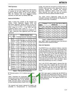
The CRC-4 multiframe alignment signal is a 001011
bit sequence that appears in PCM 30 bit position one
of the NFAS in frames 1, 3, 5, 7, 9 and 11 (see Table
4). In order to achieved CRC-4 synchronization two
consecutive CRC-4 multiframe alignment signals
must be received without error (CRCSYN = 0). See
Figure 6 for a more detailed description of the
framing functions.
7) After basic frame alignment has been achieved,
loss of frame alignment will occur any time three
consecutive incorrect FAS or NFAS are received.
Loss of basic frame alignment will reset the complete
framing algorithm.
4-249

 MITEL [ MITEL NETWORKS CORPORATION ]