MT9079
CRC Error and E-bit Counters
A similar formula can be used to provide a BERT
estimation of the transmit direction by using the E-bit
error counter, EBt.
CRC-4 errors and E-bit errors are counted by the
MT9079 in order to support compliance with CCITT
requirements. These eight bit counters are located
on page 4, addresses 1FH and 1EH respectively.
They are incremented by single error events, which
is a maximum rate of twice per CRC-4 multiframe.
A more accurate BERT estimation can be done using
the Bipolar Violation Error counter. The BPV error
counter will count violations that are not due to HDB3
encoding. The formula for this is as follows:
BERT estimation = BPV Error counter value/(256 8000 T)
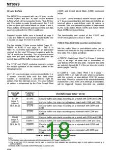
There are two maskable interrupts associated with
the CRC error and E-bit error measurement. CRCI
and EBI are initiated when the least significant bit of
the appropriate counter toggles, and CRCO and
EBO are initiated when the appropriate counter
changes from FFH to 00H.
*
*
where:
256 is the number of bits per basic frame.
8000 is the number of basic frames in one second.
T is the elapsed time in seconds.
G.821 Bit Error Rate Estimation
This assumes that one BPV error will be the result of
one bit error.
A G.821 BERT estimation for an E1 link can be done
with either the BERT counter, when it is associated
with the FAS, or the Errored Frame Alignment Signal
counter. It should be noted that the BERT counter
will be incremented once for every bit error found in
the FAS, and not just once for every FAS in error.
The formula for the link BERT estimation is as
follows:
RAI and Continuous CRC-4 Error Counter
When the receive Remote Alarm Indication is active
(RAI = 1 - bit 3 of the NFAS) and a receive E-bit
indicates a remote error (En = 0), the RCRC counter
will be incremented. This counter will count the
number of submultiframes that were received in error
at the remote end of a link during a time when layer
one capabilities were lost at that end. This eight bit
RCRC counter is located on page 4, addresses 19H.
BERT estimation = BERT counter value/(N F T)
*
*
where:
N is the number of bits verified (i.e., when the FAS
is used N = 7; when a channel is selected N = 8).
There are two maskable interrupts associated with
the RCRC counter. RCRI is initiated when the least
significant bit of the RCRC counter toggles, and
RCRO and EBO are initiated when the counter
changes from FFH to 00H.
F is the number of FAS or channels in one second
(i.e., when the FAS is used F= 4000, when a
channel is selected F = 8000).
T is the elapsed time in seconds.
Maintenance and Alarms
A similar formula can be used with the FAS error
counter.
Error Insertion
BERT estimation = FAS Error counter value/(7 4000 T).
*
*
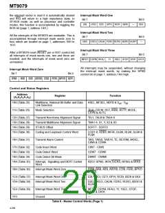
Five types of error conditions can be inserted into the
transmit PCM 30 data stream through control bits,
which are located on page 2, address 10H. These
error events include the bipolar violation errors
(BPVE), CRC-4 errors (CRCE), FAS errors (FASE),
NFAS errors (NFSE), and a loss of signal condition
(LOSE). The LOSE function overrides the HDB3
encoding function.
The CRC-4 error counter can also be used for BERT
estimation. The formula for BERT estimation using
the CRC-4 error count is as follows:
BERT estimation = CEt counter value/(2048000 T)
*
where:
2048000 is the number of bits that are
received in one second.
T is the elapsed time in seconds.
4-253

 MITEL [ MITEL NETWORKS CORPORATION ]