MT9079
channel positions of the ST-BUS and PCM 30
interface. See Tables 13, 14, 16 and 17 for CAS bit
positions in CSTo1 and CSTi2.
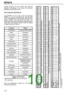
Reset Operation (Initialization)
The MT9079 can be reset using the hardware
RESET pin (see pin description for external reset
circuit requirements) or the software reset bit RST
(page 1, address 11H). During the reset state, TxA
and TxB are low. When the device emerges from its
reset state it will begin to function with the default
settings described in Table 3.
Function
Port Selection
Mode
Status
as per pins S/P & ST/SC
Termination
ST-BUS Offset
Loopbacks
00000000*
Deactivated
E8Ko
Deactivated
Transmit FAS
Transmit non-FAS
Transmit MFAS (CAS)
Data Link
C 0011011
n
1/S 1111111
n
00001111
Deactivated
CRC Interworking
Code Insert/Detect
Signalling
Activated
Deactivated
CAS (CSTi2 & CSTo1)
Deactivated
ABCD Bit Debounce
Interrupt Mask Word Zero
unmasked, all others
masked; interrupts not
suspended
Interrupts
RxMF Output
Error Insertion
Coding
Signalling Multiframe
Deactivated
10*
Tx/Rx Buffers
Counters
Deactivated
Random
Table 3 - Reset Status
*cleared by the RESET pin, but not by the
RST control bit.
See the Applications section for the MT9079
initialization procedure.
4-246

 MITEL [ MITEL NETWORKS CORPORATION ]