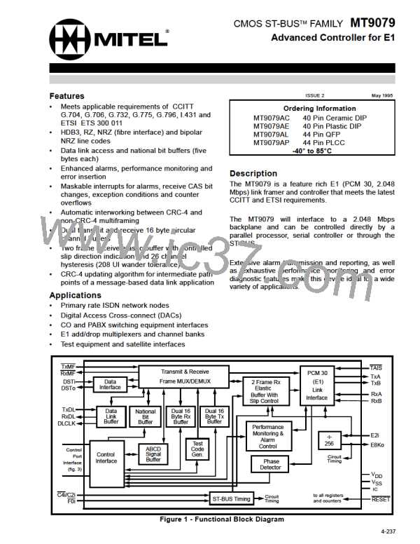
MT9079
PCM 30 Interfacing and Encoding
Bit Error Rate Counter (BR7-BR0)
Bits 7 and 6 of page 1, address 15H (COD1-0)
determine the PCM 30 format of the PCM 30
transmit and receive signals. The RZ format
(COD1-0 = 00) can be used where the line interface
is implemented with discrete components. In this
case, the pulse width and state of TxA and TxB
directly determine the width and state of the PCM 30
pulses.
An eight bit Error Rate (BERT) counter BR7 - BR0 is
located on page 4 address 18H, and is incremented
once for every bit detected in error on either the
seven frame alignment signal bits or in a selected
channel. When a selected channel is used, the data
received in this channel will be compared with the
data of the bit error rate compare word CMP7-CMP0.
See the explanation of the CDDTC control bit of the
per time slot control words (pages 7 and 8) and the
bit error rate compare word (page 2, address 11).
NRZ format (COD1-0 = 01) is not bipolar, and
therefore, only requires a single output line and a
single input line (i.e., TxA and RxA). This signal
along with a synchronous 4, 8 or 16 MHz clock can
interface to a manchester or similar encoder to
produce a self-clocking code for a fibre optic
transducer.
There are two maskable interrupts associated with
the bit error rate measurement. BERI is initiated
when the least significant bit of the BERT counter
(BR0) toggles, and BERO in initiated when the BERT
counter value changes from FFH to 00H.
The NRZB format (default COD1-0 = 10) is used for
interfacing to monolithic Line Interface Units (LIUs).
With this format pulses are present for the full bit
cell, which allows the set-up and hold times to be
meet easily.
Errored Frame Alignment Signal Counter
(EFAS7-EFAS0)
An eight bit Frame Alignment Signal Error counter
EFAS7 - EFAS0 is located on page 4 address 1AH,
and is incremented once for every receive frame
alignment signal that contains one or more errors.
The HDB3 control bit (page 1, address 15H, bit 5)
selects either HDB3 encoding or alternate mark
inversion (AMI) encoding.
There are two maskable interrupts associated with
the frame alignment signal error measurement. FERI
is initiated when the least significant bit of the
errored frame alignment signal counter toggles, and
FERO is initiated when the counter changes from
FFH to 00H.
Performance Monitoring
MT9079 Error Counters
The MT9079 has six error counters, which can be
used for maintenance testing, an ongoing measure
of the quality of a PCM 30 link and to assist the
designer in meeting specifications such as CCITT
I.431 and G.821. In parallel microprocessor and
serial microcontroller modes, all counters can be
preset or cleared by writing to the appropriate
locations. When ST-BUS access is used, this is done
by writing the value to be loaded into the counter in
the appropriate counter load word (page 2, address
18H to 1FH). The counter is loaded with the new
value when the appropriate counter load bit is
toggled (page 2, address 15H).
Bipolar Violation Error Counter (BPV15-BPV0)
The bipolar violation error counter will count bipolar
violations or encoding errors that are not part of
HDB3 encoding. This counter BPV15-BPV0 is 16
bits long (page 4, addresses 1DH and 1CH) and is
incremented once for every BPV error received. It
should be noted that when presetting or clearing the
BPV error counter, the least significant BPV counter
address should be written to before the most
significant location.
There are two maskable interrupts associated with
the bipolar violation error measurement. BPVI is
initiated when the least significant bit of the BPV
error counter toggles. BPVO is initiated when the
counter changes from FFFFH to 0000H.
Associated with each counter is a maskable event
occurrence interrupt and
a
maskable counter
overflow interrupt. Overflow interrupts are useful
when cumulative error counts are being recorded.
For example, every time the frame error counter
overflow interrupt (FERO) occurs, 256 frame errors
have been received since the last FERO interrupt.
4-252

 MITEL [ MITEL NETWORKS CORPORATION ]