MT9079
Elastic Buffer
The minimum delay through the receive elastic buffer
is approximately two channels and the maximum delay
is approximately 60 channels (RDLY=0), see Figure 5.
When control bit RDLY=0, the MT9079 has a two
frame receive elastic buffer, which absorbs wander
and low frequency jitter in multi-trunk applications.
The received PCM 30 data (RxA and RxB) is clocked
into the elastic buffer with the E2i clock and is
clocked out of the elastic buffer with the C4i/C2i
clock. The E2i extracted clock is generated from, and
is therefore phase-locked with, the receive PCM 30
data. In normal operation, the E2i clock will be
phase-locked to the C4i/C2i clock by an external
phase locked loop (PLL). Therefore, in a single trunk
system the receive data is in phase with the E2i
clock, the C4i/C2i clock is phase-locked to the E2i
clock, and the read and write positions of the elastic
buffer will remain fixed with respect to each other.
When the C4i/C2i and the E2i clocks are not
phase-locked, the rate at which data is being written
into the elastic buffer from the PCM 30 side may differ
from the rate at which it is being read out onto the
ST-BUS. If this situation persists, the delay limits
stated in the previous paragraph will be violated and
the elastic buffer will perform a controlled frame slip.
That is, the buffer pointers will be automatically
adjusted so that a full PCM 30 frame is either repeated
or lost. All frame slips occur on PCM 30 frame bound-
aries.
The RSLIP and RSLPD status bits give indication of a
slip occurrence and direction. A maskable interrupt
SLPI is also provided.
In a multi-trunk slave or loop-timed system (i.e., PABX
application) a single trunk will be chosen as a network
synchronizer, which will function as described in the
previous paragraph. The remaining trunks will use the
system timing derived form the synchronizer to clock
data out of their elastic buffers. Even though the PCM
30 signals from the network are synchronize to each
other, due to multiplexing, transmission impairments
and route diversity, these signals may jitter or wander
with respect to the synchronizer trunk signal. There-
fore, the E2i clocks of non-synchronizer trunks may
wander with respect to the E2i clock of the synchro-
nizer and the system bus. Network standards state
that, within limits, trunk interfaces must be able to
receive error-free data in the presence of jitter and
wander (refer to network requirements for jitter and
wander tolerance). The MT9079 will allow a minimum
of 26 channels (208 UI, unit intervals) of wander and
low frequency jitter before a frame slip will occur.
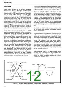
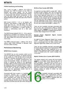
Figure 5 illustrates the relationship between the read
and write pointers of the receive elastic buffer.
Measuring clockwise from the write pointer, if the
read pointer comes within two channels of the write
pointer a frame slip will occur, which will put the read
pointer 34 channels from the write pointer.
Conversely, if the read pointer moves more than 60
channels from the write pointer, a slip will occur,
which will put the read pointer 28 channels from the
write pointer. This provides a worst case hysteresis
of 13 channels peak (26 channels peak-to-peak) or a
wander tolerance of 208 UI.
When control bit RDLY=1, the receive elastic buffer
becomes one frame long and the controlled slip
function is disabled. This is to allow the user to
control the receive throughput delay of the MT9079
in one of the following ways:
Write
Pointer
Read Pointer
Read Pointer
13 CH
60 CH
2 CH
Wander Tolerance
512 Bit
Elastic
Store
15 CH
47 CH
-13 CH
34 CH
28 CH
Read Pointer
Read Pointer
Figure 5 - Elastic Buffer Functional Diagram (208 UI Wander Tolerance)
4-248

 MITEL [ MITEL NETWORKS CORPORATION ]