MT9076
Preliminary Information
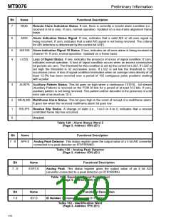
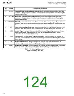
Bit
Name
Functional Description
7
RAIS
Remote Alarm Indication Status. If one, there is currently a remote alarm condition (i.e.,
received A bit is one). If zero, normal operation. Updated on a non-frame alignment frame
basis.
6
AISS
Alarm Indication Status Signal. If one, indicates that a valid AIS or all ones signal is
being received. If zero, indicates that a valid AIS signal is not being received. The criteria
for AIS detection is determined by the control bit ASEL.
5
4
AIS16S Alarm Indication Signal 16 Status. If one, indicates an all ones alarm is being received in
channel 16. If zero, normal operation. Updated on a frame basis.
LOSS
Loss of Signal Status. If one, indicates the presence of a loss of signal condition. If zero,
indicates normal operation. A loss of signal condition occurs when an excess consecutive
bit periods are zero. The threshold for this condition is set by the control bit L32Z. If L32Z is
set high the threshold is 32 successive zeros. If L32Z is set low the threshold is 192
successive zeros. A loss of signal condition terminates when an average ones density of at
least 12.5% has been received over a period of 192 contiguous pulse positions starting
with a pulse.
3
AUXPS Auxiliary Pattern Status. This bit goes on high when a continuous 101010... bit stream
(Auxiliary Pattern) is received on the PCM 30 link for a period of at least 512 bits. If zero,
auxiliary pattern is not being received. This pattern will be decoded in the presence of a bit
error rate of as much as 10-3.
2
1
0
MFALMS Multiframe Alarm Status. This bit goes high in the event of receipt of a multiframe alarm.
It goes low when the received multiframe alarm bit goes low.
RSLIPS Receive Slip Status. A change of state (i.e., 1-to-0 or 0-to-1) indicates that a receive
controlled frame slip has occurred.
- - -
Unused.
Table 129 - Alarm Status Word 2
(Page 3, Address 1BH) (E1)
Bit
Name
Functional Description
7 - 0
AP4-0
Analog Peak Detector. This status register gives the output value of a 5 bit A/D converter
connected to a peak detector on RTIP/RRING.
Table 130 - Analog Peak Detector
(Page 3, Address 1DH) (E1)
Bit
Name
Functional Description
7 - 0
ESP7-0
Analog Peak. This status register gives the output value of an 8 bit A/D
converter connected to a peak detector on RTIP/RRING.
Table 131 - Equalized Signal Peak Detect
(Page 3, Address 1EH) (E1)
Bit
Name
Functional Description
7-0
ID7-0
ID Number. Contains device code 01111000
Table 132 - Identification Word
(Page 3, Address 1FH) (E1)
116

 MITEL [ MITEL NETWORKS CORPORATION ]