MT9076
Preliminary Information
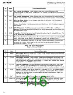
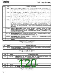
Bit
Name
Functional Description
7
1SEC One Second Timer Status. This bit changes state once every 0.5 second and is
synchronous with the 2SEC timer. This feature is not available when the device is operated in
freerun mode.
6
5
4
3
2SEC Two Second Timer Status. This bit changes state once every second and is synchronous
with the 1SEC timer.This feature is not available when the device is operated in freerun mode.
400T
8T
400 msec. Timer Status. This bit changes state when the 400 msec. CRC-4 multiframe
alignment timer expires.
8 msec. Timer Status. This bit changes state when the 8 msec. CRC-4 multiframe alignment
timer expires.
CALN CRC-4 Alignment. This bit changes state every millisecond. When CRC-4 multiframe
alignment has been achieved state changes of this bit are synchronous with the receive CRC-
4 synchronization signal.
2
1
0
KLVE
Keep Alive. This bit is high when the AIS status bit has been high for at least 100msec. This
bit will be low when AIS goes low (I.431).
T1
Timer One. This bit will be high upon loss of terminal frame synchronization persisting for 100
msec. This bit shall be low when T2 becomes high. Refer to I.431 Section 5.9.2.2.3.
T2
Timer Two. This bit will be high when the MT9076 acquires terminal frame synchronization
persisting for 10 msec. This bit shall be low when non-normal operational frames are
received. I.431 Section 5.9.2.2.3.
Table 120 - Timer Status Word
(Page 3, Address 12H) (E1)
Bit
Name
Functional Description
7
RSLIP
Receive Slip. A change of state (i.e., 1-to-0 or 0-to-1) indicates that a receive controlled
frame slip has occurred.
6
RSLPD
Receive Slip Direction. If one, indicates that the last received frame slip resulted in a
repeated frame, i.e., system clock is faster than network clock. If zero, indicates that the
last received frame slip resulted in a lost frame, i.e., system clock is slower than network
clock. Updated on an RSLIP occurance basis.
5
4
RXFRM
AUXP
Receive Frame Delay. The most significant bit of the Receive Slip Buffer Phase Status
Word. If one, the delay through the receive elastic buffer is greater than one frame in
length; if zero, the delay through the receive elastic buffer is less than one frame in length.
Auxiliary Pattern. This bit will go high when a continuous 101010... bit stream (Auxiliary
Pattern) is received on the PCM 30 link for a period of at least 512 bits. If zero, auxiliary
pattern is not being received. This pattern will be decoded in the presence of a bit error
rate of as much as 10-3.
3
RxFT
Receiver Frame Toggle. This bit toggles on the falling edge of RxTS4.
2-0
RxSBD2-0 Receive Sub Bit Delay. The three least significant bits of the Receive Slip Buffer Phase
Status Word. They indicate the clock, half clock and one eight clock cycle depth of the
phase status word sample point (bits 2, 1, o respectively).
Table 121 - Most Significant Phase Status Word
(Page 3, Address 13H) (E1)
112

 MITEL [ MITEL NETWORKS CORPORATION ]