MT9076
Preliminary Information
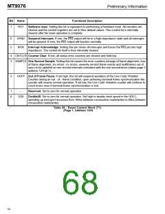
Bit
Name
Functional Description
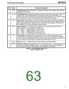
7
ESFYEL ESF Yellow Alarm. Setting this bit while in ESF mode causes a repeating pattern of eight 1’s
followed by eight 0’s to be insert onto the transmit FDL (Japan Telecom bit set low - see Data
Link Control Word) or sixteen 1’s (Japan Telecom bit set high).
6
TXSECY Transmit Secondary D4 Yellow Alarm. Setting this bit (in D4 mode) causes the S bit of
transmit frame 12 to be set.
5
4
D4YEL D4 Yellow Alarm. When set bit 2 of all DS0 channels are forced low.
TxAO
Transmit All Ones. When low, this control bit forces a framed or unframed (depending on the
state of Transmit Alarm Control bit 0) all ones to be transmit at TTIP and TRING.
3
2
1
LUA
Loop Up Activate. Setting this bit forces transmission of a framed or unframed (depending on
the state of Transmit Alarm Control bit 0) repeating pattern of 00001.
LDA
Loop Down Activate. Setting this bit forces transmission of a framed or unframed (depending
on the state of Transmit Alarm Control bit 0) repeating pattern of 001.
D4SECY D4 Secondary Alarm. Set this bit for trunks employing the secondary Yellow Alarm. The Fs bit
in the 12th frame will not be used for counting errored framing bits. If a one is received in the Fs
bit position of the 12th frame a Secondary Yellow Alarm Detect bit will be set.
0
SO
Overhead bits Override. If set, this bit forces the overhead bits to be inserted as an overlay on
any of the following alarm conditions: i) transmit all ones, ii) loop up code insertion, iii) loop
down code insertion.
Table 22 - Transmit Alarm Control Word (T1)
(Page 1, Address 11H)
60

 MITEL [ MITEL NETWORKS CORPORATION ]