Preliminary Information
MT9076
Bit
Name
Functional Description
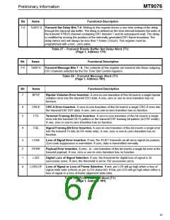
7-0
TxSD7-0 Transmit Set Delay Bits 7-0. Writing to this register forces a one time setting of the delay
through the transmit slip buffer. The delay is defined as the time interval between the write of
the transmit STBUS channel containing DS1 timeslot 1 and its subsequent read. The delay
is modified by moving the position of the internally generated DS1 frame boundary. The
delay (when set) will always be less than 1 frame (125uS). This register must be
programmed with a non - zero value.
Table 27 - Transmit Elastic Buffer Set Delay Word (T1)
(Page 1, Address 17H)
Bit
Name
Functional Description
7-0
TxM7-0 Transmit Message Bits 7 - 0. The contents of this register are transmit into those outgoing
DS1 channels selected by the Per Time Slot Control registers.
Table 28 - Transmit Message Word (T1)
(Page 1, Address 18H)
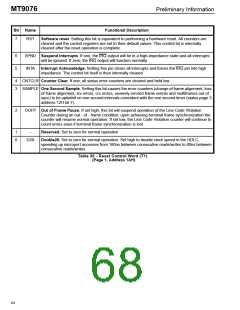
Bit
Name
Functional Description
7
BPVE
Bipolar Violation Error Insertion. A zero-to-one transition of this bit inserts a single bipolar
violation error into the transmit DS1 data. A one, zero or one-to-zero transition has no
function.
6
5
CRCE
FTE
CRC-6 Error Insertion. A zero-to-one transition of this bit inserts a single CRC-6 error into
the transmit ESF DS1 data. A one, zero or one-to-zero transition has no function.
Terminal Framing Bit Error Insertion. A zero-to-one transition of this bit inserts a single
error into the transmit D4 Ft pattern or the transmit ESF framing bit pattern (in ESF mode).
A one, zero or one-to-zero transition has no function.
4
FSE
Signal Framing Bit Error Insertion. A zero-to-one transition of this bit inserts a single error
into the transmit Fs bits (in D4 mode only). A one, zero or one-to-zero transition has no
function.
3
2
1
0
LOSE
PERR
L32Z
Loss of Signal Error Insertion. If one, the 3VJET transmits an all zeros signal (no pulses).
Zero code suppression is overridden. If zero, data is transmitted normally.
Payload Error Insertion. A zero - to - one transition of this bit inserts a single bit error in the
transmit payload. A one, zero or one-to-zero transition has no function.
Digital Loss of Signal Selection. If one, the threshold for digital loss of signal is 32
successive zeros. If zero, the threshold is set to 192 successive zeros.
LOS/LOF Loss of Signal or Loss of Frame Selection. If one, pin LOS will go high when a loss of
signal state exits (criteria as per LLOS status bit). If low, pin LOS will go high when either a
loss of signal or a loss of frame alignment state exits.
Table 29 - Error Insertion Word (T1)
(Page 1, Address 19H)
63

 MITEL [ MITEL NETWORKS CORPORATION ]