Preliminary Information
MH89760B
T1 Interface
Asynchronous
Interface
Protocol Converter
Switch Matrix
MT8980
MT89760B
ACIA
D -D
DSTi
STo1
STi1
STi0
OUTA
MT8952
•
Equal-
izer
DSTo
0
7
7
STo0
R
S
2
3
2
•
A -A
0
OUTB
RxT
CSTi0
CSTo
CSTi1
STo2
STi2
D -D
0
7
7
A -A
0
STo3
RxR
C2i
Micro
68008
ACIA
F0i
C4i
F0i
MT8952
D -D
0
A -A
0
7
7
•
•
C1.5i
R
S
2
3
2
E8Ko
•
•
D -D
0
7
7
•
•
A -A
•
•
0
MT8941
DPLL #1
ACIA
D -D
CVb
F0i
C1.5i
•
MT8952
R
0
7
7
C12i
DPLL #2
12.352
MHz
Osc.
S
2
3
2
A -A
0
•
D -D
F0b
F0i
0
7
7
•
C8Kb
A -A
0
C4b
C20
C4i
C2i
16.384
•
•
•
•
•
•
•
•
•
•
MHz
Osc.
•
•
•
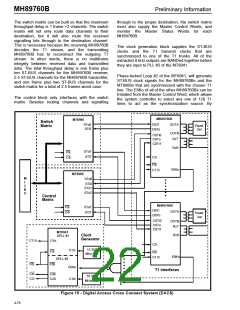
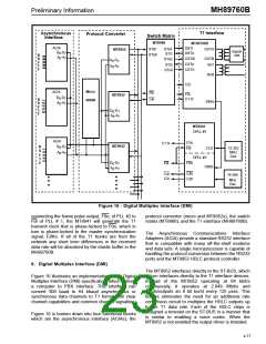
Figure 16 - Digital Multiplex Interface (DMI)
connecting the frame pulse output, F0o, of PLL #2 to
F0i of PLL # 1, the MT8941 will generate the T1
transmit clock that is phase-locked to F0o, which in
turn is phase-locked to the master synchronization
signal, E8Ko. If all of the T1 trunks are from the
network any short term differences in the received
data rate will be absorbed by the elastic buffer in the
MH89760B.
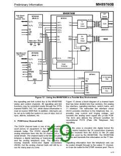
protocol converter (micro and MT8952s), the switch
matrix (MT8980), and the T1 interface (MH89760B).
The Asynchronous Communications Interface
Adapters (ACIA) provide a standard RS232 interface
that is compatible with many off-the-shelf modems
and data sets. A single microprocessor is capable of
handling the protocol conversion between the RS232
ports and the MT8952 HDLC protocol controller.
6. Digital Multiplex Interface (DMI)
The MT8952 interfaces directly to the ST-BUS, which
in turn interfaces directly to the T1 interface devices.
Instead of the MT8952 operating at 64 kbit/s
continuously, it operates at 2.048 Mbit/s and
inputs/outputs an 8 bit burst every 125 µsec. This
feature eliminates the need for an additional rate
conversion circuit to multiplex the HDLC outputs up
to the T1 data rate. Each of the HDLC chips is
assigned a timeslot on the ST-BUS in a manner that
is similar to enabling a voice codec. When the
MT8952 is not enabled the output driver is tristated.
Figure 16 illustrates an implementation of the Digital
Multiplex Interface (DMI) specification, which defines
a computer to PBX interface. This interface can
convert 300 baud to 64 kbaud asynchronous or
synchronous data channels to T1 format with clear
channel capabilities and common channel signalling.
Figure 16 is broken down into four functional blocks
which are the asynchronous interface (ACIAs), the
4-77

 MITEL [ MITEL NETWORKS CORPORATION ]