‡
Pre lim in a ry
MT9V012 - 1/6-In ch VGA CMOS Dig it a l Im a g e Se n so r
Re g ist e rs
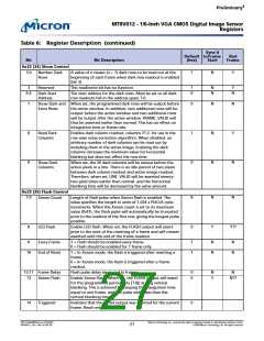
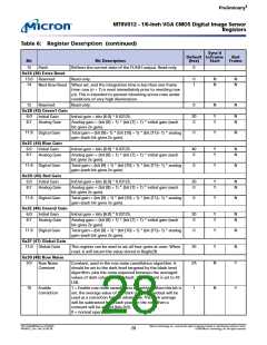
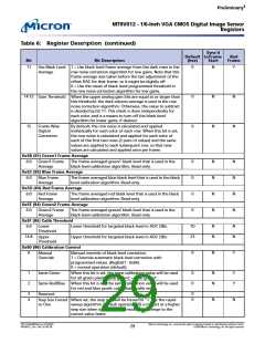
Ta b le 6: Re g ist e r De scrip t io n (co n t in u e d )
Syn c’d
De fa u lt t o Fra m e
Ba d
Fra m e
Bit
Bit De scrip t io n
(h e x)
St a rt
7
0
N
N
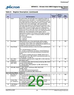
Inhibit Standby By default, asserting STANDBY places the sensor in a low-
power state. Setting this bit stops STANDBY from affecting
entry to or exit from the low-power state. See “Power
Saving Modes” on page 42.
8
9
0
0
N
N
Y
N
Show Bad
Frames
By default, the sensor only shows good frames. When this bit
is set, all frames are output.
Restart Bad
Frames
When this bit is set, a restart is forced any time a bad frame
is detected. This can shorten the delay when waiting for a
good frame, since the delay for masking out a bad frame
will be the integration time rather than the full frame time.
10
0
N
N
Toggle SADDR
By default, the sensor serial bus will respond to addresses
0xBA/0xBB. When this bit is set, the sensor serial bus will
respond to addresses 0x90/0x91. Writes to this bit are
ignored when STANDBY is asserted. See “Slave Address” on
page 16.
12
13
15
0
0
0
N
N
N
Reserved
Reserved
Reserved.
Reserved.
N
Synchronize
Changes
By default, the update for many registers is synchronized to
frame start. Setting this bit inhibits this update; register
changes will remain pending until this bit is returned to “0.”
When this bit is returned to “0,” all pending register updates
will be made on the next frame start.
0x20 (32) Re a d Mo d e - Co n t e xt B
0
1
2
0
0
0
Y
Y
Y
YM
YM
YM
Mirror Rows
Rows read out from bottom to top (upside down). When set,
row readout starts from row (Row Start + Row Size) and
continues down to (Row Start + 1). When clear, readout
starts at row start and continues to (Row Start + Row Size -
1). This ensures that the starting color is maintained.
Mirror Columns Columns read out from right to left (mirrored). When set,
column readout starts from column (Col Start + Col Size) and
continues down to (Col Start + 1). When clear, readout starts
at col start and continues to (Col Start + Col Size - 1). This
ensures that the starting color is maintained.
Row Skip 2x—
Context B
When read mode for context B is selected (Reg0xC8[3] = 1):
1 = read out two rows, skip two rows (i.e. row 8, row 9, row
12, row 13…).
0 = normal readout.
3
4
5
0
0
0
Y
Y
Y
YM
YM
YM
Column Skip
2x—Context B
When read mode for context B is selected (Reg0xC8[3] = 1):
1 = read out two columns, skip two columns (as with rows).
0 = normal readout.
Row Skip 4x
1 = read out two rows, skip six rows (i.e. row 8, row 9, row
16, row 17…).
0 = normal readout.
Column Skip 4x 1 = read out two columns, skip six columns (as with rows).
0 = normal readout.
PDF: 814eb99f/Source: 8175e929
MT9V012_2.fm - Rev. B 2/05 EN
Micron Technology, Inc., reserves the right to change products or specifications without notice.
©2004 Micron Technology, Inc. All rights reserved.
25

 MICRON [ MICRON TECHNOLOGY ]