‡
Pre lim in a ry
MT9V012 - 1/6-In ch VGA CMOS Dig it a l Im a g e Se n so r
Re g ist e rs
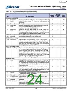
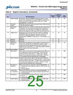
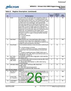
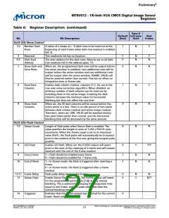
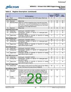
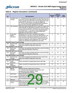
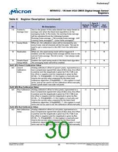
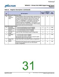
Ta b le 6: Re g ist e r De scrip t io n (co n t in u e d )
Syn c’d
De fa u lt t o Fra m e
Ba d
Fra m e
Bit
Bit De scrip t io n
(h e x)
St a rt
15
0
Flash
Reflects the current state of the FLASH output. Read-only.
0x24 (36) Ext ra Re se t
13:0
14
0
1
N
N
N
N
Reserved
Read-only.
Next Row Reset When set, and the integration time is less than one frame
time; row (n + 1) is reset immediately prior to resetting row
(n). This is intended to prevent blooming across rows under
conditions of very high illumination.
15
0
N
N
Reserved
Read-only.
0x2B (43) Gre e n 1 Ga in
6:0
8:7
20
0
Y
Y
N
N
Initial Gain
Initial gain = bits [6:0] * 0.03125.
Analog Gain
Analog gain = (bit [8] + 1) * (bit [7] + 1) * initial gain (each
bit gives 2x gain).
11:9
0
Y
N
Digital Gain
Total gain = (bit [9]+ 1) * (bit [10] + 1) * (bit [11]+ 1) * analog
gain (each bit gives 2x gain).
0x2C (44) Blu e Ga in
6:0
8:7
40
0
Y
Y
N
N
Initial Gain
Initial gain = bits [6:0] * 0.03125.
Analog Gain
Analog gain = (bit [8] + 1) * (bit [7] + 1) * initial gain (each
bit gives 2x gain).
11:9
0
Y
N
Digital Gain
Total gain = (bit [9] + 1) * (bit [10] + 1) * (bit [11]+ 1) * analog
gain (each bit gives 2x gain).
0x2D (45) Re d Ga in
6:0
8:7
20
0
Y
Y
N
N
Initial Gain
Initial gain = bits [6:0] * 0.03125.
Analog Gain
Analog gain = (bit [8] + 1) * (bit [7] + 1) * initial gain (each
bit gives 2x gain).
11:9
0
Y
N
Digital Gain
Total gain = (bit [9] + 1) * (bit [10] + 1) * (bit [11]+ 1) * analog
gain (each bit gives 2x gain).
0x2E (46) Gre e n 2 Ga in
6:0
8:7
20
0
Y
Y
N
N
Initial Gain
Initial gain = bits [6:0] * 0.03125.
Analog Gain
Analog gain = (bit [8] + 1) * (bit [7] + 1) * initial gain (each
bit gives 2x gain).
11:9
0
Y
Y
N
N
N
Y
Digital Gain
Total gain = (bit [9] + 1) * (bit [10] + 1) * (bit [11]+ 1) * analog
gain (each bit gives 2x gain).
0x2F (47) Glo b a l Ga in
11:0
20
2A
Global Gain
This register can be used to set all four gains at once. When
read, it will return the value stored in Reg0x2B.
0x30 (48) Ro w No ise
9:0
Row Noise
Constant
Constant, used in the row noise cancellation algorithm. It
should be set to the dark level targeted by the black level
algorithm, plus the noise expected between the averaged
values of dark columns. At default, the constant is set to 42
LSB.
10
1
N
Y
Enable
Correction
1 = Enable row noise cancellation algorithm. When this bit is
set, the average value of the dark columns readout will be
used as a correction for the whole row. The dark average
will be subtracted from each pixel on the row, then a
constant will be added (bits 9:0).
0 = normal operation.
PDF: 814eb99f/Source: 8175e929
MT9V012_2.fm - Rev. B 2/05 EN
Micron Technology, Inc., reserves the right to change products or specifications without notice.
©2004 Micron Technology, Inc. All rights reserved.
28

 MICRON [ MICRON TECHNOLOGY ]