‡
Pre lim in a ry
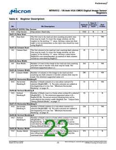
MT9V012 - 1/6-In ch VGA CMOS Dig it a l Im a g e Se n so r
Re g ist e rs
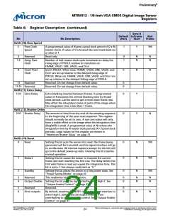
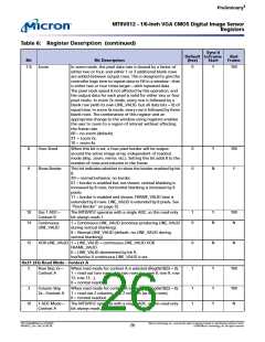
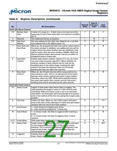
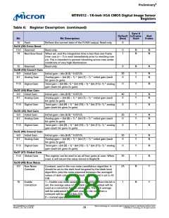
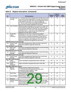
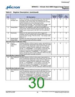
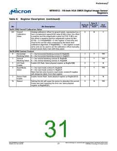
Ta b le 6: Re g ist e r De scrip t io n (co n t in u e d )
Syn c’d
De fa u lt t o Fra m e
Ba d
Fra m e
Bit
Bit De scrip t io n
(h e x)
St a rt
0x22 (34) Sh o w Co n t ro l
2:0
7
N
Y
Number Dark
Rows
A value of n causes (n + 1) dark rows to be read out at the
beginning of each frame when dark-row readout is enabled
(bit 3).
3
1
0
N
N
Y
N
Reserved
This read/write bit has no function.
6:4
Dark Start
Address
The start address for the dark rows. Must be set so all dark-
row readouts fall in the address space 7:0.
7
8
9
0
1
0
N
N
N
N
Y
N
Show Dark and When set, the programmed dark rows will be output before
Extra Rows
the active window. In addition, two additional rows will be
output before the active window and two additional rows
will be output after the active window. FRAME_VALID will
thus be asserted earlier than normal. This has no effect on
integration time or frame rate.
Read Dark
Columns
Enables dark column readout, columns 21:2, for use in the
row-wise noise correction algorithm. When disabled, an
arbitrary number of dark columns can be read out by
including them in the active image. Enabling the dark
columns increases the minimum value for horizontal
blanking but does not affect the row time.
Show Dark
Columns
When set, the 20 dark columns will be output before the
active pixels in a line. There is an idle period of two pixels
between dark column readout and active image readout.
Therefore, when set, LINE_VALID will be asserted twenty-
two pixel times earlier than normal, and the horizontal
blanking time will be decreased by the same amount.
0x23 (35) Fla sh Co n t ro l
7:0
8
0
N
Y
N
Xenon Count
Length of flash pulse when Xenon flash is enabled. The
value specifies the length in units of 1,024 x PIXCLK cycle
increments. When the Xenon count is set to its maximum
value (0xFF), the flash pulse will automatically be truncated
prior to the readout of the first row, giving the longest pulse
possible.
8
Y??
LED Flash
Enable LED flash. When set, the FLASH output will assert
prior to the start of the resetting of a frame and will remain
asserted until the end of the frame readout.
9
1
1
N
N
N
N
Every Frame
End of Reset
1 = Flash should be enabled every frame.
0 = Flash should be enabled for 1 frame only.
10
1 = In Xenon mode, the flash is triggered after resetting a
frame.
0 = In Xenon mode, the flash is triggered after a frame
readout.
12:11
13
0
0
N
Y
N
Frame Delay
Xenon Flash
Flash pulse delay measured in frames.
N??
Enable Xenon flash. When set, the FLASH output will assert
for the programmed period (bits [7:0]) during vertical
blanking. This is achieved by keeping the integration time
equal to one frame, and the pulse width less than the
vertical blanking time.
14
0
Triggered
Indicates that the FLASH output was asserted for the current
frame. Read-only.
PDF: 814eb99f/Source: 8175e929
MT9V012_2.fm - Rev. B 2/05 EN
Micron Technology, Inc., reserves the right to change products or specifications without notice.
©2004 Micron Technology, Inc. All rights reserved.
27

 MICRON [ MICRON TECHNOLOGY ]