2 MEG x 16
ASYNC/PAGE/BURST FLASH MEMORY
CLOCK CONFIGURATION
The clock configuration configures the starting burst
cycle, outputdata, andWAIT#signaltobeassertedonthe
rising or falling edge of the clock.
is the maximum delay, equal to the latency counter
setting.
The delay happens only once during a continuous
burst access. If the burst never crosses an eight-word
boundary, the WAIT# is not asserted. The WAIT# informs
the system if this output delay occurs.
BURST WRAP
The burst wrap option, RCR3, signals if a four- or an
eight-word linear burst access wraps within the burst
length or whether it crosses the eight-word boundary. In
wrap mode (RCR3 = 0) the four- or eight-word access will
wrap within the four or eight words, respectively. In no-
wrap mode (RCR3 = 1), the device operates similarly to a
continuous burst. For example, in a four-word burst, no-
wrap mode, the possible linear burst sequences that do
not assert WAIT# are:
WAIT# SIGNAL IN BURST MODE
In the continuous burst mode or in the four- or eight-
word burst mode with no wrap (RCR3 = 1), the output
WAIT# informs the system when data is valid. When
WAIT# is asserted during delay (RCR8 = 0), WAIT# = 1
indicates valid data, and WAIT# = 0 indicates invalid
data. If RCR8 = 0, WAIT# is asserted on the same cycle on
whichthedelayoccurs. IfRCR8=1, WAIT#isassertedone
cycle before the delay occurs.
0-1-2-3
1-2-3-4
2-3-4-5
3-4-5-6
4-5-6-7
8-9-10-11
9-10-11-12
10-11-12-13
11-12-13-14
12-13-14-15
BLOCK LOCKING
The Flash devices provide a flexible locking scheme
that allows each block to be individually locked or un-
locked with no latency.
The devices offer two-level protection for the blocks.
The first level allows software-only control of block lock-
ing (for data, which needs to be changed frequently),
while the second level requires hardware interaction be-
forelockingcanbechanged(codewhichdoesnotrequire
frequent updates).
Control signals WP#, DQ1, and DQ0 define the state
of a block; for example, state [001] means WP# = 0, DQ1 =
0 and DQ0 = 1.
The worst-case delay is seen at the end of the eight-
word boundary: 7-8-9-10 and 15-16-17-18. In a four-
word burst, wrap mode, no WAIT# is asserted, and the
possible wrap sequences are:
0-1-2-3
1-2-3-0
2-3-0-1
3-0-1-2
4-5-6-7
5-6-7-4
6-7-4-5
7-4-5-6
8-9-10-11
9-10-11-8
etc.
When the continuous burst option is selected, the inter-
nal address wraps to 000000h if the device is read past the
last address.
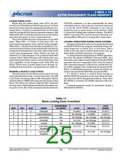
Table 11 defines all of the possible locking states.
BURST LENGTH
NOTE: All blocks are software-locked upon comple-
The burst length defines the number of words the
deviceoutputs. Thedevicesupportsaburstlengthoffour
or eight words. The device can also be set in continuous
burst mode. In this mode the device linearly outputs data
until the internal burst counter reaches the end of the
burstable address space. RCR2 sets the burst length.
tion of a power-up sequence.
LOCKED STATE
After a power-up sequence completion, or after a
resetsequence,allblocksarelocked(states[001]or[101]).
This means full protection from alteration. Any PRO-
GRAM or ERASE operations attempted on a locked block
will return an error on bit SR1 of the status register. The
status of a locked block can be changed to unlocked or
lock down using the appropriate software commands.
Writing the lock command sequence, 60h followed by
01h, can lock an unlocked block.
CONTINUOUS BURST LENGTH
During continuous burst mode operation, the Flash
memory may have an output delay when the burst se-
quence crosses the first eight-word boundary. Also, in
four- or eight-word bursts with the burst wrap set to no
wrap (RCR3 = 1), the Flash memory may have an output
delay when the burst sequence crosses the first eight-
word boundary. The starting address dictates whether or
not a delay occurs. If the starting address is aligned with
an eight-word boundary, the delay is not seen. For a four-
word burst, if the starting address is aligned with a four-
word boundary, a delay is not seen. If the starting address
is at the end of an eight-word boundary, the output delay
UNLOCKED STATE
Unlocked blocks (states [000], [100], [110]) can be
programmed or erased. All unlocked blocks return to the
locked state when the device is reset or powered down.
An unlocked block can be locked or locked down using
the appropriate software command sequence, 60h fol-
lowed by D0h (see Table 4).
2 Meg x 16 Async/Page/Burst Flash Memory
MT28F322D20FH_4.p65 – Rev. 4, Pub. 7/02
Micron Technology, Inc., reserves the right to change products or specifications without notice.
24
©2002, Micron Technology, Inc.

 MICRON [ MICRON TECHNOLOGY ]