PIC24FJ64GA104 FAMILY
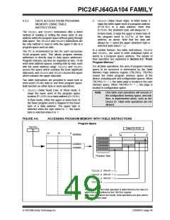
2. TBLRDH (Table Read High): In Word mode, it
maps the entire upper word of a program address
(P<23:16>) to a data address. Note that
D<15:8>, the ‘phantom’ byte, will always be ‘0’.
4.3.2
DATA ACCESS FROM PROGRAM
MEMORY USING TABLE
INSTRUCTIONS
The TBLRDL and TBLWTL instructions offer a direct
method of reading or writing the lower word of any
address within the program space without going through
data space. The TBLRDHand TBLWTHinstructions are
the only method to read or write the upper 8 bits of a
program space word as data.
In Byte mode, it maps the upper or lower byte of
the program word to D<7:0> of the data
address, as above. Note that the data will
always be ‘0’ when the upper ‘phantom’ byte is
selected (byte select = 1).
In a similar fashion, two table instructions, TBLWTH
and TBLWTL, are used to write individual bytes or
words to a program space address. The details of
their operation are explained in Section 5.0 “Flash
Program Memory”.
The PC is incremented by two for each successive
24-bit program word. This allows program memory
addresses to directly map to data space addresses.
Program memory can thus be regarded as two, 16-bit
word-wide address spaces, residing side by side, each
with the same address range. TBLRDL and TBLWTL
access the space which contains the least significant
data word, and TBLRDHand TBLWTHaccess the space
which contains the upper data byte.
For all table operations, the area of program memory
space to be accessed is determined by the Table
Memory Page Address register (TBLPAG). TBLPAG
covers the entire program memory space of the
device, including user and configuration spaces. When
TBLPAG<7> = 0, the table page is located in the user
memory space. When TBLPAG<7> = 1, the page is
located in configuration space.
Two table instructions are provided to move byte or
word-sized (16-bit) data to and from program space.
Both function as either byte or word operations.
1. TBLRDL (Table Read Low): In Word mode, it
maps the lower word of the program space
location (P<15:0>) to a data address (D<15:0>).
Note:
Only table read operations will execute in
the configuration memory space, and only
then, in implemented areas, such as the
Device ID. Table write operations are not
allowed.
In Byte mode, either the upper or lower byte of
the lower program word is mapped to the lower
byte of a data address. The upper byte is
selected when the byte select is ‘1’; the lower
byte is selected when it is ‘0’.
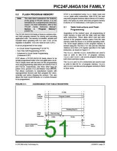
FIGURE 4-6:
ACCESSING PROGRAM MEMORY WITH TABLE INSTRUCTIONS
Program Space
TBLPAG
02
Data EA<15:0>
23
15
0
000000h
23
16
8
0
00000000
00000000
00000000
00000000
020000h
030000h
‘Phantom’ Byte
TBLRDH.B (Wn<0> = 0)
TBLRDL.B (Wn<0> = 1)
TBLRDL.B (Wn<0> = 0)
TBLRDL.W
The address for the table operation is determined by the data EA
within the page defined by the TBLPAG register.
Only read operations are shown; write operations are also valid in
the user memory area.
800000h
2010 Microchip Technology Inc.
DS39951C-page 49

 MICROCHIP [ MICROCHIP ]