PIC24FJ64GA104 FAMILY
4.2.5
SOFTWARE STACK
4.3
Interfacing Program and Data
Memory Spaces
In addition to its use as a working register, the W15
register in PIC24F devices is also used as a Software
Stack Pointer. The pointer always points to the first
available free word and grows from lower to higher
addresses. It predecrements for stack pops and
post-increments for stack pushes, as shown in
Figure 4-4. Note that for a PC push during any CALL
instruction, the MSB of the PC is zero-extended before
the push, ensuring that the MSB is always clear.
The PIC24F architecture uses a 24-bit wide program
space and a 16-bit wide data space. The architecture is
also a modified Harvard scheme, meaning that data
can also be present in the program space. To use this
data successfully, it must be accessed in a way that
preserves the alignment of information in both spaces.
Aside from normal execution, the PIC24F architecture
provides two methods by which program space can be
accessed during operation:
Note:
A PC push during exception processing
will concatenate the SRL register to the
MSB of the PC prior to the push.
• Using table instructions to access individual bytes
or words anywhere in the program space
The Stack Pointer Limit Value (SPLIM) register, associ-
ated with the Stack Pointer, sets an upper address
boundary for the stack. SPLIM is uninitialized at Reset.
As is the case for the Stack Pointer, SPLIM<0> is
forced to ‘0’ because all stack operations must be
word-aligned. Whenever an EA is generated using
W15 as a source or destination pointer, the resulting
address is compared with the value in SPLIM. If the
contents of the Stack Pointer (W15) and the SPLIM
register are equal, and a push operation is performed,
a stack error trap will not occur. The stack error trap will
occur on a subsequent push operation. Thus, for
example, if it is desirable to cause a stack error trap
when the stack grows beyond address 2000h in RAM,
initialize the SPLIM with the value, 1FFEh.
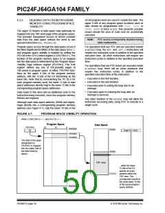
• Remapping a portion of the program space into
the data space (program space visibility)
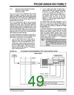
Table instructions allow an application to read or write
to small areas of the program memory. This makes the
method ideal for accessing data tables that need to be
updated from time to time. It also allows access to all
bytes of the program word. The remapping method
allows an application to access a large block of data on
a read-only basis, which is ideal for look-ups from a
large table of static data; it can only access the least
significant word of the program word.
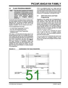
4.3.1
ADDRESSING PROGRAM SPACE
Since the address ranges for the data and program
spaces are 16 and 24 bits, respectively, a method is
needed to create a 23-bit or 24-bit program address
from 16-bit data registers. The solution depends on the
interface method to be used.
Similarly, a Stack Pointer underflow (stack error) trap is
generated when the Stack Pointer address is found to
be less than 0800h. This prevents the stack from
interfering with the Special Function Register (SFR)
space.
For table operations, the 8-bit Table Memory Page
Address (TBLPAG) register is used to define a 32K word
region within the program space. This is concatenated
with a 16-bit EA to arrive at a full 24-bit program space
address. In this format, the Most Significant bit of
TBLPAG is used to determine if the operation occurs in
the user memory (TBLPAG<7> = 0) or the configuration
memory (TBLPAG<7> = 1).
A write to the SPLIM register should not be immediately
followed by an indirect read operation using W15.
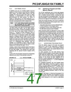
FIGURE 4-4:
CALL STACK FRAME
0000h
15
0
For remapping operations, the 8-bit Program Space
Visibility Page Address (PSVPAG) register is used to
define a 16K word page in the program space. When
the Most Significant bit of the EA is ‘1’, PSVPAG is con-
catenated with the lower 15 bits of the EA to form a
23-bit program space address. Unlike table operations,
this limits remapping operations strictly to the user
memory area.
PC<15:0>
000000000
W15 (before CALL)
PC<22:16>
<Free Word>
W15 (after CALL)
POP : [--W15]
PUSH: [W15++]
Table 4-27 and Figure 4-5 show how the program EA is
created for table operations and remapping accesses
from the data EA. Here, P<23:0> refers to a program
space word, whereas D<15:0> refers to a data space
word.
2010 Microchip Technology Inc.
DS39951C-page 47

 MICROCHIP [ MICROCHIP ]