PIC24FJ64GA104 FAMILY
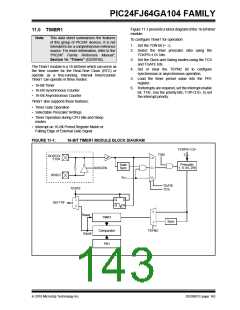
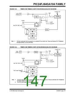
Figure 11-1 presents a block diagram of the 16-bit timer
module.
11.0 TIMER1
Note:
This data sheet summarizes the features
of this group of PIC24F devices. It is not
intended to be a comprehensive reference
source. For more information, refer to the
“PIC24F Family Reference Manual”,
Section 14. “Timers” (DS39704).
To configure Timer1 for operation:
1. Set the TON bit (= 1).
2. Select the timer prescaler ratio using the
TCKPS<1:0> bits.
3. Set the Clock and Gating modes using the TCS
and TGATE bits.
The Timer1 module is a 16-bit timer which can serve as
the time counter for the Real-Time Clock (RTC) or
operate as a free-running, interval timer/counter.
Timer1 can operate in three modes:
4. Set or clear the TSYNC bit to configure
synchronous or asynchronous operation.
5. Load the timer period value into the PR1
register.
• 16-Bit Timer
6. If interrupts are required, set the interrupt enable
bit, T1IE. Use the priority bits, T1IP<2:0>, to set
the interrupt priority.
• 16-Bit Synchronous Counter
• 16-Bit Asynchronous Counter
Timer1 also supports these features:
• Timer Gate Operation
• Selectable Prescaler Settings
• Timer Operation during CPU Idle and Sleep
modes
• Interrupt on 16-Bit Period Register Match or
Falling Edge of External Gate Signal
FIGURE 11-1:
16-BIT TIMER1 MODULE BLOCK DIAGRAM
TCKPS<1:0>
TON
2
SOSCO/
1x
01
00
T1CK
Prescaler
1, 8, 64, 256
Gate
Sync
SOSCEN
SOSCI
TCY
TGATE
TCS
TGATE
1
0
Q
Q
D
Set T1IF
CK
0
Reset
Equal
TMR1
Sync
1
TSYNC
Comparator
PR1
2010 Microchip Technology Inc.
DS39951C-page 143

 MICROCHIP [ MICROCHIP ]