PIC24FJ64GA104 FAMILY
To configure Timer2/3 or Timer4/5 for 32-bit operation:
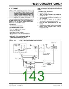
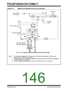
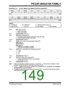
12.0 TIMER2/3 AND TIMER4/5
1. Set the T32 bit (T2CON<3> or T4CON<3> = 1).
Note:
This data sheet summarizes the features
2. Select the prescaler ratio for Timer2 or Timer4
using the TCKPS<1:0> bits.
of this group of PIC24F devices. It is not
intended to be a comprehensive reference
source. For more information, refer to the
“PIC24F Family Reference Manual”,
Section 14. “Timers” (DS39704).
3. Set the Clock and Gating modes using the TCS
and TGATE bits. If TCS is set to an external
clock, RPINRx (TxCK) must be configured to an
available
RPn
pin.
See
Section
The Timer2/3 and Timer4/5 modules are 32-bit timers,
which can also be configured as four independent 16-bit
timers with selectable operating modes.
10.4 “Peripheral Pin Select (PPS)” for more
information.
4. Load the timer period value. PR3 (or PR5) will
contain the most significant word of the value
while PR2 (or PR4) contains the least significant
word.
As 32-bit timers, Timer2/3 and Timer4/5 can each
operate in three modes:
• Two Independent 16-Bit Timers with All 16-Bit
Operating modes (except Asynchronous Counter
mode)
5. If interrupts are required, set the interrupt enable
bit, T3IE or T5IE; use the priority bits, T3IP<2:0>
or T5IP<2:0>, to set the interrupt priority. Note
that while Timer2 or Timer4 controls the timer,
the interrupt appears as a Timer3 or Timer5
interrupt.
• Single 32-Bit Timer
• Single 32-Bit Synchronous Counter
They also support these features:
6. Set the TON bit (= 1).
• Timer Gate Operation
• Selectable Prescaler Settings
The timer value, at any point, is stored in the register
pair, TMR3:TMR2 (or TMR5:TMR4). TMR3 (TMR5)
always contains the most significant word of the count,
while TMR2 (TMR4) contains the least significant word.
• Timer Operation during Idle and Sleep modes
• Interrupt on a 32-Bit Period Register Match
• ADC Event Trigger (Timer4/5 only)
To configure any of the timers for individual 16-bit
operation:
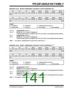
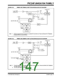
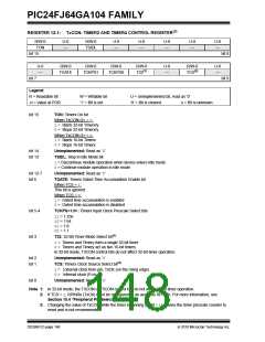
Individually, all four of the 16-bit timers can function as
synchronous timers or counters. They also offer the
features listed above, except for the ADC event trigger;
this is implemented only with Timer5. The operating
modes and enabled features are determined by setting
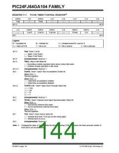
the appropriate bit(s) in the T2CON, T3CON, T4CON
and T5CON registers. T2CON and T4CON are shown
in generic form in Register 12-1; T3CON and T5CON
are shown in Register 12-2.
1. Clear the T32 bit corresponding to that timer
(T2CON<3> for Timer2 and Timer3 or
T4CON<3> for Timer4 and Timer5).
2. Select the timer prescaler ratio using the
TCKPS<1:0> bits.
3. Set the Clock and Gating modes using the TCS
and TGATE bits. See Section 10.4 “Peripheral
Pin Select (PPS)” for more information.
For 32-bit timer/counter operation, Timer2 and Timer4
are the least significant word; Timer3 and Timer4 are
the most significant word of the 32-bit timers.
4. Load the timer period value into the PRx register.
5. If interrupts are required, set the interrupt enable
bit, TxIE; use the priority bits, TxIP<2:0>, to set
the interrupt priority.
Note:
For 32-bit operation, T3CON and T5CON
control bits are ignored. Only T2CON and
T4CON control bits are used for setup and
control. Timer2 and Timer4 clock and gate
inputs are utilized for the 32-bit timer
modules, but an interrupt is generated with
the Timer3 or Timer5 interrupt flags.
6. Set the TON bit (TxCON<15> = 1).
2010 Microchip Technology Inc.
DS39951C-page 145

 MICROCHIP [ MICROCHIP ]