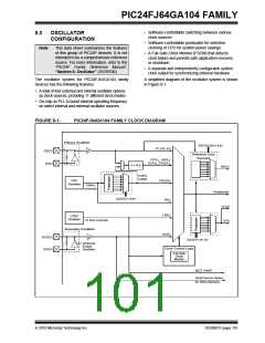
PIC24FJ64GA104 FAMILY
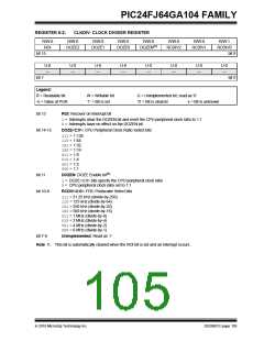
REGISTER 8-2:
CLKDIV: CLOCK DIVIDER REGISTER
R/W-0
ROI
R/W-0
R/W-0
R/W-0
R/W-0
DOZEN(1)
R/W-0
R/W-0
R/W-1
DOZE2
DOZE1
DOZE0
RCDIV2
RCDIV1
RCDIV0
bit 15
bit 8
U-0
—
U-0
—
U-0
—
U-0
—
U-0
—
U-0
—
U-0
—
U-0
—
bit 7
bit 0
Legend:
R = Readable bit
W = Writable bit
‘1’ = Bit is set
U = Unimplemented bit, read as ‘0’
‘0’ = Bit is cleared x = Bit is unknown
-n = Value at POR
bit 15
ROI: Recover on Interrupt bit
1= Interrupts clear the DOZEN bit and reset the CPU peripheral clock ratio to 1:1
0= Interrupts have no effect on the DOZEN bit
bit 14-12
DOZE<2:0>: CPU Peripheral Clock Ratio Select bits
111= 1:128
110= 1:64
101= 1:32
100= 1:16
011= 1:8
010= 1:4
001= 1:2
000= 1:1
bit 11
DOZEN: DOZE Enable bit(1)
1= DOZE<2:0> bits specify the CPU peripheral clock ratio
0= CPU peripheral clock ratio set to 1:1
bit 10-8
RCDIV<2:0>: FRC Postscaler Select bits
111= 31.25 kHz (divide-by-256)
110= 125 kHz (divide-by-64)
101= 250 kHz (divide-by-32)
100= 500 kHz (divide-by-16)
011= 1 MHz (divide-by-8)
010= 2 MHz (divide-by-4)
001= 4 MHz (divide-by-2)
000= 8 MHz (divide-by-1)
bit 7-0
Unimplemented: Read as ‘0’
Note 1: This bit is automatically cleared when the ROI bit is set and an interrupt occurs.
2010 Microchip Technology Inc.
DS39951C-page 105

 MICROCHIP [ MICROCHIP ]