PIC24FJ64GA104 FAMILY
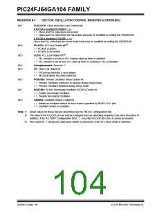
REGISTER 8-1:
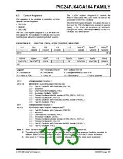
OSCCON: OSCILLATOR CONTROL REGISTER (CONTINUED)
bit 7
CLKLOCK: Clock Selection Lock Enabled bit
If FSCM is enabled (FCKSM1 = 1):
1= Clock and PLL selections are locked
0= Clock and PLL selections are not locked and may be modified by setting the OSWEN bit
If FSCM is disabled (FCKSM1 = 0):
Clock and PLL selections are never locked and may be modified by setting the OSWEN bit.
bit 6
bit 5
IOLOCK: I/O Lock Enable bit(2)
1= I/O lock is active
0= I/O lock is not active
LOCK: PLL Lock Status bit(3)
1= PLL module is in lock or PLL module start-up timer is satisfied
0= PLL module is out of lock, PLL start-up timer is running or PLL is disabled
bit 4
bit 3
Unimplemented: Read as ‘0’
CF: Clock Fail Detect bit
1= FSCM has detected a clock failure
0= No clock failure has been detected
bit 2
bit 1
bit 0
POSCEN: Primary Oscillator Sleep Enable bit
1= Primary Oscillator continues to operate during Sleep mode
0= Primary Oscillator disabled during Sleep mode
SOSCEN: 32 kHz Secondary Oscillator (SOSC) Enable bit
1= Enable Secondary Oscillator
0= Disable Secondary Oscillator
OSWEN: Oscillator Switch Enable bit
1= Initiate an oscillator switch to clock source specified by NOSC<2:0> bits
0= Oscillator switch is complete
Note 1: Reset values for these bits are determined by the FNOSC Configuration bits.
2: The state of the IOLOCK bit can only be changed once an unlocking sequence has been executed. In
addition, if the IOL1WAY Configuration bit is ‘1’, once the IOLOCK bit is set, it cannot be cleared.
3: Also resets to ‘0’ during any valid clock switch or whenever a non-PLL clock mode is selected.
DS39951C-page 104
2010 Microchip Technology Inc.

 MICROCHIP [ MICROCHIP ]