PIC24FJ64GA104 FAMILY
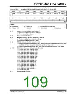
REGISTER 8-3:
OSCTUN: FRC OSCILLATOR TUNE REGISTER
U-0
—
U-0
—
U-0
—
U-0
—
U-0
—
U-0
—
U-0
—
U-0
—
bit 15
bit 8
U-0
—
U-0
—
R/W-0
TUN5(1)
R/W-0
TUN4(1)
R/W-0
TUN3(1)
R/W-0
TUN2(1)
R/W-0
TUN1(1)
R/W-0
TUN0(1)
bit 7
bit 0
Legend:
R = Readable bit
-n = Value at POR
W = Writable bit
‘1’ = Bit is set
U = Unimplemented bit, read as ‘0’
‘0’ = Bit is cleared x = Bit is unknown
bit 15-6
bit 5-0
Unimplemented: Read as ‘0’
TUN<5:0>: FRC Oscillator Tuning bits(1)
011111= Maximum frequency deviation
011110=
000001=
000000= Center frequency, oscillator is running at factory calibrated frequency
111111=
100001=
100000= Minimum frequency deviation
Note 1: Increments or decrements of TUN<5:0> may not change the FRC frequency in equal steps over the FRC
tuning range and may not be monotonic.
8.4.1
ENABLING CLOCK SWITCHING
8.4
Clock Switching Operation
To enable clock switching, the FCKSM Configuration bits
in CW2 must be programmed to ‘00’. (Refer to
Section 25.1 “Configuration Bits” for further details.)
If the FCKSM Configuration bits are unprogrammed
(‘1x’), the clock switching function and Fail-Safe Clock
Monitor function are disabled. This is the default setting.
With few limitations, applications are free to switch
between any of the four clock sources (POSC, SOSC,
FRC and LPRC) under software control and at any
time. To limit the possible side effects that could result
from this flexibility, PIC24F devices have a safeguard
lock built into the switching process.
The NOSCx control bits (OSCCON<10:8>) do not
control the clock selection when clock switching is dis-
abled. However, the COSCx bits (OSCCON<14:12>)
will reflect the clock source selected by the FNOSCx
Configuration bits.
Note:
The Primary Oscillator mode has three
different submodes (XT, HS and EC)
which are determined by the POSCMDx
Configuration bits. While an application
can switch to and from Primary Oscillator
mode in software, it cannot switch
between the different primary submodes
without reprogramming the device.
The OSWEN control bit (OSCCON<0>) has no effect
when clock switching is disabled. It is held at ‘0’ at all
times.
DS39951C-page 106
2010 Microchip Technology Inc.

 MICROCHIP [ MICROCHIP ]