PIC24FJ64GA104 FAMILY
In general, the crystal circuit connections should be as
short as possible. It is also good practice to surround
the crystal circuit with a ground loop or ground plane.
For more information on crystal circuit design, please
refer to Section 6 “Oscillator” (DS39700) of the
“PIC24F Family Reference Manual”. Additional infor-
mation is also available in these Microchip Application
Notes:
8.5
Secondary Oscillator (SOSC)
8.5.1
BASIC SOSC OPERATION
PIC24FJ64GA104 family devices do not have to set the
SOSCEN bit to use the Secondary Oscillator. Any
module requiring the SOSC (such as RTCC, Timer1 or
DSWDT) will automatically turn on the SOSC when the
clock signal is needed. The SOSC, however, has a long
start-up time. To avoid delays for peripheral start-up, the
SOSC can be manually started using the SOSCEN bit.
• AN826, “Crystal Oscillator Basics and Crystal
Selection for rfPIC® and PICmicro® Devices”
(DS00826)
• AN849, “Basic PICmicro® Oscillator Design”
To use the Secondary Oscillator, the SOSCSEL<1:0>
bits (CW3<9:8>) must be configured in an oscillator
mode – either ‘11’ or ‘01’. Setting SOSCSEL to ‘00’
configures the SOSC pins for Digital mode, enabling
digital I/O functionality on the pins. Digital functionality
will not be available if the SOSC is configured in either
of the oscillator modes.
(DS00849).
8.6
Reference Clock Output
In addition to the CLKO output (FOSC/2) available in
certain oscillator modes, the device clock in the
PIC24FJ64GA104 family devices can also be config-
ured to provide a reference clock output signal to a port
pin. This feature is available in all oscillator configura-
tions and allows the user to select a greater range of
clock submultiples to drive external devices in the
application.
8.5.2
LOW-POWER SOSC OPERATION
The Secondary Oscillator can operate in two distinct
levels of power consumption based on device configu-
ration. In Low-Power mode, the oscillator operates in a
low drive strength, low-power state. By default, the
oscillator uses a higher drive strength, and therefore,
requires more power. The Secondary Oscillator Mode
Configuration bits, SOSCSEL<1:0> (CW3<9:8>),
determine the oscillator’s power mode. Programming
the SOSCSEL bits to ‘01’ selects low-power operation.
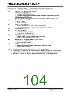
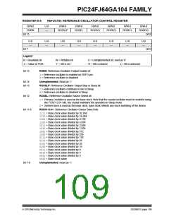
This reference clock output is controlled by the
REFOCON register (Register 8-4). Setting the ROEN
bit (REFOCON<15>) makes the clock signal available
on the REFO pin. The RODIV bits (REFOCON<11:8>)
enable the selection of 16 different clock divider
options.
The lower drive strength of this mode makes the SOSC
more sensitive to noise and requires a longer start-up
time. When Low-Power mode is used, care must be
taken in the design and layout of the SOSC circuit to
ensure that the oscillator starts up and oscillates
properly.
The ROSSLP and ROSEL bits (REFOCON<13:12>)
control the availability of the reference output during
Sleep mode. The ROSEL bit determines if the oscillator
on OSC1 and OSC2, or the current system clock source,
is used for the reference clock output. The ROSSLP bit
determines if the reference source is available on REFO
when the device is in Sleep mode.
8.5.3
EXTERNAL (DIGITAL) CLOCK
MODE (SCLKI)
To use the reference clock output in Sleep mode, both
the ROSSLP and ROSEL bits must be set. The device
clock must also be configured for one of the primary
modes (EC, HS or XT); otherwise, if the POSCEN bit is
not also set, the oscillator on OSC1 and OSC2 will be
powered down when the device enters Sleep mode.
Clearing the ROSEL bit allows the reference output
frequency to change as the system clock changes
during any clock switches.
The SOSC can also be configured to run from an
external 32 kHz clock source, rather than the internal
oscillator. In this mode, also referred to as Digital mode,
the clock source provided on the SCLKI pin is used to
clock any modules that are configured to use the
Secondary Oscillator. In this mode, the crystal driving
circuit is disabled and the SOSCEN bit (OSCCON<1>)
has no effect.
8.5.4
SOSC LAYOUT CONSIDERATIONS
The pinout limitations on low pin count devices, such as
those in the PIC24FJ64GA104 family, may make the
SOSC more susceptible to noise than other PIC24F
devices. Unless proper care is taken in the design and
layout of the SOSC circuit, this external noise may
introduce inaccuracies into the oscillator’s period.
DS39951C-page 108
2010 Microchip Technology Inc.

 MICROCHIP [ MICROCHIP ]