PIC24FJ64GA104 FAMILY
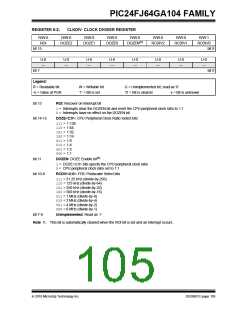
The CLKDIV register (Register 8-2) controls the
features associated with Doze mode, as well as the
postscaler for the FRC Oscillator.
8.3
Control Registers
The operation of the oscillator is controlled by three
Special Function Registers:
The OSCTUN register (Register 8-3) allows the user to
fine tune the FRC Oscillator over a range of approxi-
mately ±12%. Each bit increment or decrement
changes the factory calibrated frequency of the FRC
Oscillator by a fixed amount.
• OSCCON
• CLKDIV
• OSCTUN
The OSCCON register (Register 8-1) is the main con-
trol register for the oscillator. It controls clock source
switching and allows the monitoring of clock sources.
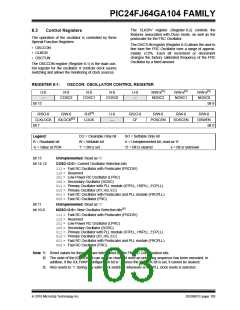
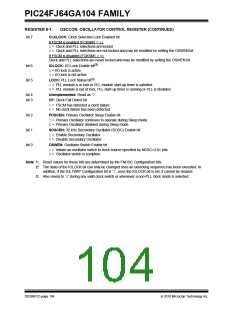
REGISTER 8-1:
OSCCON: OSCILLATOR CONTROL REGISTER
U-0
—
R-0
R-0
R-0
U-0
—
R/W-x(1)
NOSC2
R/W-x(1)
NOSC1
R/W-x(1)
NOSC0
COSC2
COSC1
COSC0
bit 15
bit 8
R/SO-0
R/W-0
IOLOCK(2)
R-0(3)
LOCK
U-0
—
R/CO-0
CF
R/W-0
R/W-0
R/W-0
CLKLOCK
bit 7
POSCEN
SOSCEN
OSWEN
bit 0
Legend:
CO = Clearable Only bit
W = Writable bit
SO = Settable Only bit
U = Unimplemented bit, read as ‘0’
‘0’ = Bit is cleared x = Bit is unknown
R = Readable bit
-n = Value at POR
‘1’ = Bit is set
bit 15
Unimplemented: Read as ‘0’
bit 14-12
COSC<2:0>: Current Oscillator Selection bits
111= Fast RC Oscillator with Postscaler (FRCDIV)
110= Reserved
101= Low-Power RC Oscillator (LPRC)
100= Secondary Oscillator (SOSC)
011= Primary Oscillator with PLL module (XTPLL, HSPLL, ECPLL)
010= Primary Oscillator (XT, HS, EC)
001= Fast RC Oscillator with Postscaler and PLL module (FRCPLL)
000= Fast RC Oscillator (FRC)
bit 11
Unimplemented: Read as ‘0’
bit 10-8
NOSC<2:0>: New Oscillator Selection bits(1)
111= Fast RC Oscillator with Postscaler (FRCDIV)
110= Reserved
101= Low-Power RC Oscillator (LPRC)
100= Secondary Oscillator (SOSC)
011= Primary Oscillator with PLL module (XTPLL, HSPLL, ECPLL)
010= Primary Oscillator (XT, HS, EC)
001= Fast RC Oscillator with Postscaler and PLL module (FRCPLL)
000= Fast RC Oscillator (FRC)
Note 1: Reset values for these bits are determined by the FNOSC Configuration bits.
2: The state of the IOLOCK bit can only be changed once an unlocking sequence has been executed. In
addition, if the IOL1WAY Configuration bit is ‘1’, once the IOLOCK bit is set, it cannot be cleared.
3: Also resets to ‘0’ during any valid clock switch or whenever a non-PLL clock mode is selected.
2010 Microchip Technology Inc.
DS39951C-page 103

 MICROCHIP [ MICROCHIP ]