PIC18F2480/2580/4480/4580
Reset. For wake-ups from Sleep, the INTOSC or
postscaler clock sources can be selected by setting the
IRCF2:IRCF0 bits prior to entering Sleep mode.
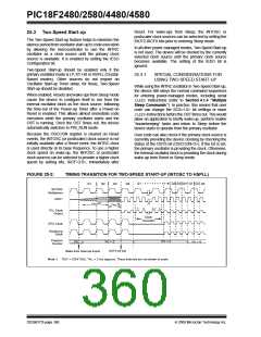
25.3 Two-Speed Start-up
The Two-Speed Start-up feature helps to minimize the
latency period from oscillator start-up to code execution
by allowing the microcontroller to use the INTRC
oscillator as a clock source until the primary clock
source is available. It is enabled by setting the IESO
Configuration bit.
In all other power-managed modes, Two-Speed Start-up
is not used. The device will be clocked by the currently
selected clock source until the primary clock source
becomes available. The setting of the IESO bit is
ignored.
Two-Speed Start-up should be enabled only if the
primary oscillator mode is LP, XT, HS or HSPLL (Crystal-
Based modes). Other sources do not require an
Oscillator Start-up Timer delay; for these, Two-Speed
Start-up should be disabled.
25.3.1
SPECIAL CONSIDERATIONS FOR
USING TWO-SPEED START-UP
While using the INTRC oscillator in Two-Speed Start-up,
the device still obeys the normal command sequences
for entering power-managed modes, including serial
SLEEP instructions (refer to Section 4.1.4 “Multiple
Sleep Commands”). In practice, this means that user
code can change the SCS<1:0> bit settings or issue
SLEEPinstructions before the OST times out. This would
allow an application to briefly wake-up, perform routine
“housekeeping” tasks and return to Sleep before the
device starts to operate from the primary oscillator.
When enabled, Resets and wake-ups from Sleep mode
cause the device to configure itself to run from the
internal oscillator block as the clock source, following
the time-out of the Power-up Timer after a Power-on
Reset is enabled. This allows almost immediate code
execution while the primary oscillator starts and the
OST is running. Once the OST times out, the device
automatically switches to PRI_RUN mode.
Because the OSCCON register is cleared on Reset
events, the INTOSC (or postscaler) clock source is not
initially available after a Reset event; the INTRC clock
is used directly at its base frequency. To use a higher
clock speed on wake-up, the INTOSC or postscaler
clock sources can be selected to provide a higher clock
speed by setting bits, IRCF<2:0>, immediately after
User code can also check if the primary clock source is
currently providing the device clocking by checking the
status of the OSTS bit (OSCCON<3>). If the bit is set,
the primary oscillator is providing the clock. Otherwise,
the internal oscillator block is providing the clock during
wake-up from Reset or Sleep mode.
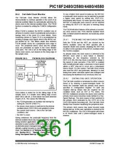
FIGURE 25-2:
TIMING TRANSITION FOR TWO-SPEED START-UP (INTOSC TO HSPLL)
Q3
Q4
Q1
Q2 Q3 Q4 Q1 Q2 Q3
Q1
Q2
INTOSC
Multiplexer
OSC1
(1)
(1)
TOST
TPLL
1
2
n-1 n
PLL Clock
Output
Clock
Transition
CPU Clock
Peripheral
Clock
Program
Counter
PC + 4
PC + 6
PC
PC + 2
OSTS bit Set
Note 1: TOST = 1024 TOSC; TPLL = 2 ms (approx). These intervals are not shown to scale.
Wake from Interrupt Event
DS39637D-page 360
© 2009 Microchip Technology Inc.

 MICROCHIP [ MICROCHIP ]