PIC18F2480/2580/4480/4580
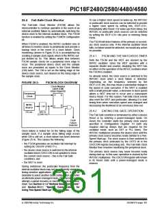
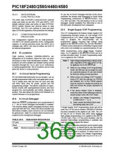
FIGURE 25-4:
FSCM TIMING DIAGRAM
Sample Clock
Oscillator
Failure
Device
Clock
Output
CM Output
(Q)
Failure
Detected
OSCFIF
CM Test
CM Test
CM Test
Note:
The device clock is normally at a much higher frequency than the sample clock. The relative frequencies in this
example have been chosen for clarity.
For oscillator modes involving a crystal or resonator
(HS, HSPLL, LP or XT), the situation is somewhat
different. Since the oscillator may require a start-up
time considerably longer than the FCSM sample clock
time, a false clock failure may be detected. To prevent
this, the internal oscillator block is automatically
configured as the device clock and functions until the
primary clock is stable (the OST and PLL timers have
timed out). This is identical to Two-Speed Start-up
mode. Once the primary clock is stable, the INTRC
returns to its role as the FSCM source.
25.4.3
FSCM INTERRUPTS IN
POWER-MANAGED MODES
By entering a power-managed mode, the clock
multiplexer selects the clock source selected by the
OSCCON register. Fail-Safe Clock Monitoring of
the power-managed clock source resumes in the
power-managed mode.
If an oscillator failure occurs during power-managed
operation, the subsequent events depend on whether
or not the oscillator failure interrupt is enabled. If
enabled (OSCFIF = 1), code execution will be clocked
by the INTOSC multiplexer. An automatic transition
back to the failed clock source will not occur.
Note:
The same logic that prevents false oscilla-
tor failure interrupts on POR, or wake from
Sleep, will also prevent the detection of
the oscillator’s failure to start at all follow-
ing these events. This can be avoided by
monitoring the OSTS bit and using a
timing routine to determine if the oscillator
is taking too long to start. Even so, no
oscillator failure interrupt will be flagged.
If the interrupt is disabled, subsequent interrupts while
in Idle mode will cause the CPU to begin executing
instructions while being clocked by the INTOSC
source.
25.4.4
POR OR WAKE-UP FROM SLEEP
The FSCM is designed to detect oscillator failure at any
point after the device has exited Power-on Reset
(POR) or low-power Sleep mode. When the primary
device clock is EC, RC or INTRC modes, monitoring
can begin immediately following these events.
As noted in Section 25.3.1 “Special Considerations
for Using Two-Speed Start-up”, it is also possible to
select another clock configuration and enter an alternate
power-managed mode while waiting for the primary
clock to become stable. When the new power-managed
mode is selected, the primary clock is disabled.
DS39637D-page 362
© 2009 Microchip Technology Inc.

 MICROCHIP [ MICROCHIP ]