PIC18F2480/2580/4480/4580
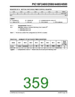
REGISTER 25-14: WDTCON: WATCHDOG TIMER CONTROL REGISTER
U-0
—
U-0
—
U-0
—
U-0
—
U-0
—
U-0
—
U-0
—
R/W-0
SWDTEN(1)
bit 0
bit 7
Legend:
R = Readable bit
-n = Value at POR
W = Writable bit
‘1’ = Bit is set
U = Unimplemented bit, read as ‘0’
‘0’ = Bit is cleared x = Bit is unknown
bit 7-1
bit 0
Unimplemented: Read as ‘0’
SWDTEN: Software Controlled Watchdog Timer Enable bit(1)
1= Watchdog Timer is on
0= Watchdog Timer is off
Note 1: This bit has no effect if the Configuration bit, WDTEN, is enabled.
TABLE 25-2: SUMMARY OF WATCHDOG TIMER REGISTERS
Reset
Values
Name
Bit 7
Bit 6
Bit 5
Bit 4
Bit 3
Bit 2
Bit 1
Bit 0
on Page:
RCON
WDTCON
IPEN
—
SBOREN
—
—
—
RI
—
TO
—
PD
—
POR
—
BOR
54
SWDTEN
56
Legend: — = unimplemented, read as ‘0’. Shaded cells are not used by the Watchdog Timer.
© 2009 Microchip Technology Inc.
DS39637D-page 359

 MICROCHIP [ MICROCHIP ]