PIC17C4X
5.1
Interrupt Status Register (INTSTA)
Note: T0IF, INTF, T0CKIF, or PEIF will be set by
the specified condition, even if the corre-
sponding interrupt enable bit is clear (inter-
rupt disabled) or the GLINTD bit is set (all
interrupts disabled).
The Interrupt Status/Control register (INTSTA) records
the individual interrupt requests in flag bits, and con-
tains the individual interrupt enable bits (not for the
peripherals).
Care should be taken when clearing any of the INTSTA
register enable bits when interrupts are enabled
(GLINTD is clear). If any of the INTSTA flag bits (T0IF,
INTF, T0CKIF, or PEIF) are set in the same instruction
cycle as the corresponding interrupt enable bit is
cleared, the device will vector to the reset address
(0x00).
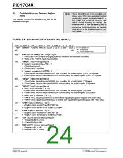
The PEIF bit is a read only, bit wise OR of all the periph-
eral flag bits in the PIR register (Figure 5-4).
When disabling any of the INTSTA enable bits, the
GLINTD bit should be set (disabled).
FIGURE 5-2: INTSTA REGISTER (ADDRESS: 07h, UNBANKED)
R - 0
PEIF
R/W - 0 R/W - 0 R/W - 0 R/W - 0 R/W - 0 R/W - 0 R/W - 0
T0CKIF T0IF INTF PEIE T0CKIE T0IE INTE
bit0
R = Readable bit
W = Writable bit
- n = Value at POR reset
bit7
bit 7:
bit 6:
bit 5:
bit 4:
bit 3:
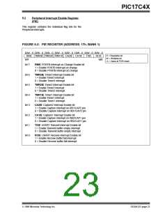
PEIF: Peripheral Interrupt Flag bit
This bit is the OR of all peripheral interrupt flag bits AND’ed with their corresponding enable bits.
1 = A peripheral interrupt is pending
0 = No peripheral interrupt is pending
T0CKIF: External Interrupt on T0CKI Pin Flag bit
This bit is cleared by hardware, when the interrupt logic forces program execution to vector (18h).
1 = The software specified edge occurred on the RA1/T0CKI pin
0 = The software specified edge did not occur on the RA1/T0CKI pin
T0IF: TMR0 Overflow Interrupt Flag bit
This bit is cleared by hardware, when the interrupt logic forces program execution to vector (10h).
1 = TMR0 overflowed
0 = TMR0 did not overflow
INTF: External Interrupt on INT Pin Flag bit
This bit is cleared by hardware, when the interrupt logic forces program execution to vector (08h).
1 = The software specified edge occurred on the RA0/INT pin
0 = The software specified edge did not occur on the RA0/INT pin
PEIE: Peripheral Interrupt Enable bit
This bit enables all peripheral interrupts that have their corresponding enable bits set.
1 = Enable peripheral interrupts
0 = Disable peripheral interrupts
bit 2:
bit 1:
bit 0:
T0CKIE: External Interrupt on T0CKI Pin Enable bit
1 = Enable software specified edge interrupt on the RA1/T0CKI pin
0 = Disable interrupt on the RA1/T0CKI pin
T0IE: TMR0 Overflow Interrupt Enable bit
1 = Enable TMR0 overflow interrupt
0 = Disable TMR0 overflow interrupt
INTE: External Interrupt on RA0/INT Pin Enable bit
1 = Enable software specified edge interrupt on the RA0/INT pin
0 = Disable software specified edge interrupt on the RA0/INT pin
DS30412C-page 22
1996 Microchip Technology Inc.

 MICROCHIP [ MICROCHIP ]