PIC17C4X
5.4
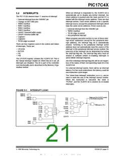
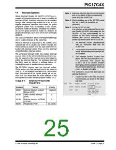
Interrupt Operation
Note 1: Individual interrupt flag bits are set regard-
less of the status of their corresponding
mask bit or the GLINTD bit.
Global Interrupt Disable bit, GLINTD (CPUSTA<4>),
enables all unmasked interrupts (if clear) or disables all
interrupts (if set). Individual interrupts can be disabled
through their corresponding enable bits in the INTSTA
register. Peripheral interrupts need either the global
peripheral enable PEIE bit disabled, or the specific
peripheral enable bit disabled. Disabling the peripher-
als via the global peripheral enable bit, disables all
peripheral interrupts. GLINTD is set on reset (interrupts
disabled).
Note 2: When disabling any of the INTSTA enable
bits, the GLINTD bit should be set
(disabled).
Note 3: For the PIC17C42 only:
If an interrupt occurs while the Global Inter-
rupt Disable (GLINTD) bit is being set, the
GLINTD bit may unintentionally be re-
enabled by the user’s Interrupt Service
Routine (the RETFIE instruction). The
events that would cause this to occur are:
The RETFIEinstruction allows returning from interrupt
and re-enable interrupts at the same time.
1. An interrupt occurs simultaneously
with an instruction that sets the
GLINTD bit.
When an interrupt is responded to, the GLINTD bit is
automatically set to disable any further interrupt, the
return address is pushed onto the stack and the PC is
loaded with interrupt vector. There are four interrupt
vectors to reduce interrupt latency.
2. The program branches to the Interrupt
vector and executes the Interrupt Ser-
vice Routine.
The peripheral interrupt vector has multiple interrupt
sources. Once in the peripheral interrupt service rou-
tine, the source(s) of the interrupt can be determined by
polling the interrupt flag bits. The peripheral interrupt
flag bit(s) must be cleared in software before re-
enabling interrupts to avoid continuous interrupts.
3. The Interrupt Service Routine com-
pletes with the execution of the RET-
FIE instruction. This causes the
GLINTD bit to be cleared (enables
interrupts), and the program returns to
the instruction after the one which was
meant to disable interrupts.
The PIC17C4X devices have four interrupt vectors.
These vectors and their hardware priority are shown in
Table 5-1. If two enabled interrupts occur “at the same
time”, the interrupt of the highest priority will be ser-
viced first. This means that the vector address of that
interrupt will be loaded into the program counter (PC).
The method to ensure that interrupts are
globally disabled is:
1. Ensure that the GLINTD bit was set by
the instruction, as shown in the follow-
ing code:
TABLE 5-1:
INTERRUPT VECTORS/
PRIORITIES
LOOP
BSF
CPUSTA, GLINTD ; Disable Global
; Interrupt
BTFSS CPUSTA, GLINTD ; Global Interrupt
; Disabled?
Address
Vector
Priority
GOTO
LOOP
; NO, try again
; YES, continue
; with program
; low
0008h
0010h
0018h
0020h
External Interrupt on RA0/
INT pin (INTF)
1 (Highest)
TMR0 overflow interrupt
(T0IF)
2
3
External Interrupt on T0CKI
(T0CKIF)
Peripherals (PEIF)
4 (Lowest)
1996 Microchip Technology Inc.
DS30412C-page 25

 MICROCHIP [ MICROCHIP ]