PIC17C4X
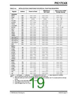
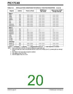
TABLE 4-4:
Register
INITIALIZATION CONDITIONS FOR SPECIAL FUNCTION REGISTERS (Cont.’d)
MCLR Reset
WDT Reset
Wake-up from SLEEP
through interrupt
Address
Power-on Reset
Bank 2
TMR1
10h
11h
12h
13h
14h
15h
16h
17h
xxxx xxxx
xxxx xxxx
xxxx xxxx
xxxx xxxx
xxxx xxxx
xxxx xxxx
xxxx xxxx
xxxx xxxx
uuuu uuuu
uuuu uuuu
uuuu uuuu
uuuu uuuu
uuuu uuuu
uuuu uuuu
uuuu uuuu
uuuu uuuu
uuuu uuuu
uuuu uuuu
uuuu uuuu
uuuu uuuu
uuuu uuuu
uuuu uuuu
uuuu uuuu
uuuu uuuu
TMR2
TMR3L
TMR3H
PR1
PR2
PR3/CA1L
PR3/CA1H
Bank 3
PW1DCL
PW2DCL
PW1DCH
PW2DCH
CA2L
10h
11h
12h
13h
14h
15h
16h
17h
xx-- ----
xx-- ----
xxxx xxxx
xxxx xxxx
xxxx xxxx
xxxx xxxx
0000 0000
0000 0000
uu-- ----
uu-- ----
uuuu uuuu
uuuu uuuu
uuuu uuuu
uuuu uuuu
0000 0000
0000 0000
uu-- ----
uu-- ----
uuuu uuuu
uuuu uuuu
uuuu uuuu
uuuu uuuu
uuuu uuuu
uuuu uuuu
CA2H
TCON1
TCON2
Unbanked
PRODL (5)
PRODH (5)
18h
19h
xxxx xxxx
xxxx xxxx
uuuu uuuu
uuuu uuuu
uuuu uuuu
uuuu uuuu
Legend: u= unchanged, x= unknown, -= unimplemented read as '0', q= value depends on condition.
Note 1: One or more bits in INTSTA, PIR will be affected (to cause wake-up).
2: When the wake-up is due to an interrupt and the GLINTD bit is cleared, the PC is loaded with the interrupt
vector.
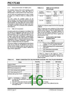
3: See Table 4-3 for reset value of specific condition.
4: Only applies to the PIC17C42.
5: Does not apply to the PIC17C42.
DS30412C-page 20
1996 Microchip Technology Inc.

 MICROCHIP [ MICROCHIP ]