PIC17C75X
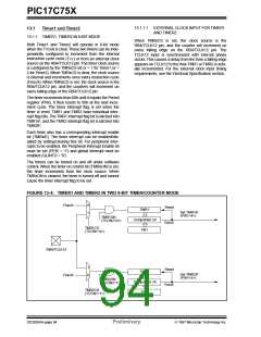
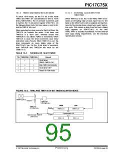
13.1.2 TIMER1 AND TIMER2 IN 16-BIT MODE
13.1.2.1 EXTERNAL CLOCK INPUT FOR
TMR2:TMR1
To select 16-bit mode, set the T16 bit. In this mode
TMR2 and TMR1 are concatenated to form a 16-bit
timer (TMR2:TMR1). The 16-bit timer increments until
it matches the 16-bit period register (PR2:PR1). On
the following timer clock, the timer value is reset to 0h,
and the TMR1IF bit is set.
When TMR1CS is set, the 16-bit TMR2:TMR1 incre-
ments on the falling edge of clock input TCLK12. The
input on the RB4/TCLK12 pin is sampled and synchro-
nized by the internal phase clocks twice every instruc-
tion cycle. This causes a delay from the time a falling
edge appears on RB4/TCLK12 to the time
TMR2:TMR1 is actually incremented. For the external
clock input timing requirements, see the Electrical
Specification section.
When selecting the clock source for the16-bit timer, the
TMR1CS bit controls the entire 16-bit timer and
TMR2CS is a “don’t care”, however ensure that
TMR2ON is set (allows TMR2 to increment). When
TMR1CS is clear, the timer increments once every
instruction cycle (Fosc/4). When TMR1CS is set, the
timer increments on every falling edge of the
RB4/TCLK12 pin. For the 16-bit timer to increment,
both TMR1ON and TMR2ON bits must be set
(Table 13-2).
TABLE 13-2: TURNING ON 16-BIT TIMER
T16 TMR2ON TMR1ON
Result
16-bit timer
1
1
1
(TMR2:TMR1) ON
Only TMR1 increments
16-bit timer OFF
1
1
0
0
x
1
1
0
1
Timers in 8-bit mode
FIGURE 13-5: TMR2 AND TMR1 IN 16-BIT TIMER/COUNTER MODE
1
RB4/TCLK12
0
Fosc/4
TMR1ON
(TCON2<0>)
MSB
LSB
TMR1CS
(TCON1<0>)
Reset
TMR2 x 8
TMR1 x 8
<8>
Comparator x16
Equal
Set Interrupt TMR1IF
(PIR1<4>)
PR2 x 8
PR1 x 8
1997 Microchip Technology Inc.
Preliminary
DS30264A-page 95

 MICROCHIP [ MICROCHIP ]