PIC17C75X
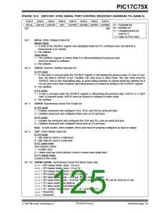
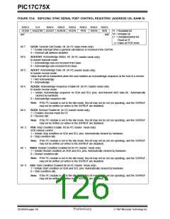
FIGURE 15-6: SSPCON2: SYNC SERIAL PORT CONTROL REGISTER2 (ADDRESS 12h, BANK 6)
R/W-0
GCEN ACKSTAT ACKDT ACKEN RCEN
bit7
R-0
R/W-0
R/W-0
R/W-0
R/W-0 R/W-0 R/W-0
PEN RSEN SEN
bit0
R =Readable bit
W = Writable bit
U =Unimplemented bit,
Read as ‘0’
- n =Value at POR reset
bit 7:
GCEN: General Call Enable bit (In I2C slave mode only)
1 = Enable interrupt when a general call address is received in the SSPSR.
0 = General call address disabled.
bit 6:
bit 5:
ACKSTAT: Acknowledge Status bit (In I2C master mode only)
In master transmit mode:
1 = Acknowledge was not received from slave
0 = Acknowledge was received from slave
ACKDT: Acknowledge Data bit (In I2C master mode only)
In master receive mode:
Value that will be transmitted when the user initiates an Acknowledge sequence at the end of a receive.
1 = Not Acknowledge
0 = Acknowledge
bit 4:
ACKEN: Acknowledge Sequence Enable bit (In I2C master mode only).
In master receive mode:
1 = Initiate Acknowledge sequence on SDA and SCL pins, and transmit AKD data bit. Automatically
cleared by hardware.
0 = Acknowledge sequence idle
2
Note: If the I C module is not in the idle mode, this bit may not be set (no spooling), and the SSPBUF
may not be written (or writes to the SSPBUF are disabled).
bit 3:
RCEN: Receive Enable bit (In I2C master mode only).
1 = Enables Receive mode for I2C
0 = Receive idle
2
Note: If the I C module is not in the idle mode, this bit may not be set (no spooling), and the SSPBUF
may not be written (or writes to the SSPBUF are disabled).
bit 2:
PEN: Stop Condition Enable bit (In I2C master mode only).
SCK release control
1 = Initiate Stop condition on SDA and SCL pins. Automatically cleared by hardware.
0 = Stop condition idle
2
Note: If the I C module is not in the idle mode, this bit may not be set (no spooling), and the SSPBUF
may not be written (or writes to the SSPBUF are disabled).
bit 1: RSEN: Restart Condition Enabled bit (In I2C master mode only)
1 = Initiate Restart condition on SDA and SCL pins. Automatically cleared by hardware.
0 = Restart condition idle.
2
Note: If the I C module is not in the idle mode, this bit may not be set (no spooling), and the SSPBUF
may not be written (or writes to the SSPBUF are disabled)
bit 0: SEN: Start Condition Enabled bit (In I2C master mode only)
1 = Initiate Start condition on SDA and SCL pins. Automatically cleared by hardware.
0 = Start condition idle.
2
Note: If the I C module is not in the idle mode, this bit may not be set (no spooling), and the SSPBUF
may not be written (or writes to the SSPBUF are disabled).
DS30264A-page 126
Preliminary
1997 Microchip Technology Inc.

 MICROCHIP [ MICROCHIP ]