PIC17C75X
2
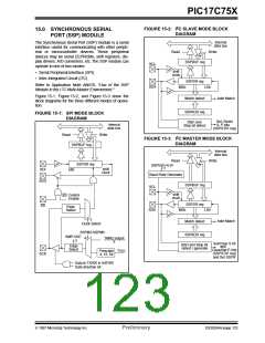
FIGURE 15-2: I C SLAVE MODE BLOCK
DIAGRAM
15.0 SYNCHRONOUS SERIAL
PORT (SSP) MODULE
Internal
The Synchronous Serial Port (SSP) module is a serial
interface useful for communicating with other periph-
eral or microcontroller devices. These peripheral
devices may be serial EEPROMs, shift registers, dis-
play drivers, A/D converters, etc. The SSP module can
operate in one of two modes:
data bus
Read
Write
SSPBUF reg
SSPSR reg
SCL
SDA
shift
clock
• Serial Peripheral Interface (SPI)
2
• Inter-Integrated Circuit (I C)
Refer to Application Note AN578, "Use of the SSP
MSb
LSb
2
Module in the I C Multi-Master Environment."
Figure 15-1, Figure 15-2, and Figure 15-3 show the
block diagrams for the three different modes of opera-
tion.
Addr Match
Match detect
SSPADD reg
FIGURE 15-1: SPI MODE BLOCK
DIAGRAM
Set, Reset
S, P bits
(SSPSTAT reg)
Start and
Stop bit detect
Internal
data bus
Read
Write
2
FIGURE 15-3: I C MASTER MODE BLOCK
DIAGRAM
SSPBUF reg
SSPSR reg
Internal
data bus
Read
Write
SSPADD<6:0>
7
shift
clock
SDI
bit0
Baud Rate Generator
SDO
SSPBUF reg
SSPSR reg
SCL
shift
clock
Control
Enable
SS
SS
Edge
Select
SDA
MSb
LSb
2
Addr Match
Match detect
SSPADD reg
Clock Select
SSPM3:SSPM0
SMP:CKE
2
4
TMR2 output
2
Set/Clear S bit
and
Clear/Set P, bits
(SSPSTAT reg)
Start and Stop bit
detect / generate
Edge
Select
TOSC
Prescaler
4, 16, 64
SCK
and Set SSPIF
Data to TX/RX in SSPSR
Data direction bit
1997 Microchip Technology Inc.
Preliminary
DS30264A-page 123

 MICROCHIP [ MICROCHIP ]