3 .0 V/3 .3 V Ad ju s t a b le Mic ro p ro c e s s o r
S u p e rvis o ry Circ u it s
out period (t ), the state of MR is ignored if PFO is exter-
RP
_______________De t a ile d De s c rip t io n
nally forced low, to facilitate enabling the battery fresh-
ness seal. MR has an internal 70µA pull-up current, so it
can be left open if it is not used. This input can be driven
with TTL- or CMOS-logic levels, or with open-drain/collec-
tor outputs. Connect a normally open momentary switch
from MR to GND to create a manual-reset function; exter-
nal debounce circuitry is not required. If MR is driven
from long cables or the device is used in a noisy environ-
ment, connect a 0.1µF capacitor from MR to ground to
provide additional noise immunity.
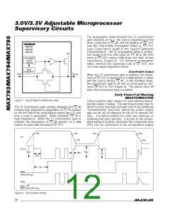
Ge n e ra l Tim in g Ch a ra c t e ris t ic s
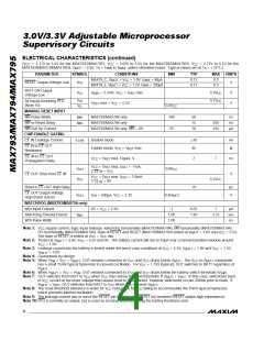
The MAX793/MAX794/MAX795 are designed for 3.3V
and 3V systems, and provide a number of supervisory
functions (see the Selector Guide on the front page).
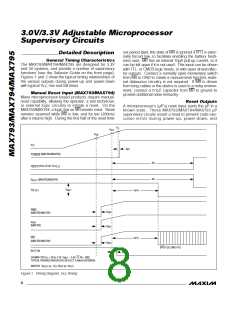
Figures 1 and 2 show the typical timing relationships of
the various outputs during power-up and power-down
with typical V rise and fall times.
CC
Ma n u a l Re s e t In p u t (MAX7 9 3 /MAX7 9 4 )
Many microprocessor-based products require manual-
reset capability, allowing the operator, a test technician,
or external logic circuitry to initiate a reset. On the
MAX793/MAX794, a logic low on MR asserts reset. Reset
Re s e t Ou t p u t s
A microprocessor’s (µP’s) reset input starts the µP in a
known s ta te . The s e MAX793/MAX794/MAX795 µP
supervisory circuits assert a reset to prevent code exe-
c ution e rrors d uring p owe r-up , p owe r-d own, a nd
remains asserted while MR is low, and for t (200ms)
RP
after it returns high. During the first half of the reset time-
V
LL
V
RST
V
SW
V
CC
5µs
V
(MAX793/MAX794)
LOWLINE
34/MAX795
t
RP
V
RESET
(PULLED UP TO V )
CC
t
RP
V
RESET
(MAX793/MAX794)
V
BATT
V
CE OUT
t
/
RP 2
V
WDO
25µs
25µs
(MAX793/MAX794)
V
BOK
(MAX793)
PFO
t /
RP 2
(MAX793/MAX794)
25µs
(PFO FOLLOWS PFI)
BATT ON
25µs
SHOWN FOR V = 0V to 3.3V, V
= 3.6V, CE IN = GND.
CC
BATT
TYPICAL PROPAGATION DELAYS REFLECT A 40mV OVERDRIVE.
MAX794: V = V (V / V
)
RESET IN CC RST IN RST
Figure 1. Timing Diagram, V Rising
CC
8
_______________________________________________________________________________________

 MAXIM [ MAXIM INTEGRATED PRODUCTS ]