SXT6051 STM-1/0 SDH Overhead Terminator
.
• The serial RSOH & MSOH interface (TSOH
input pin)
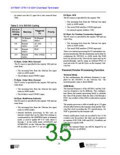
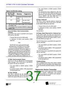
Table 6: K2 RDI Bit Coding
K2<2:0> RDI
• The Internal Processing configured by 30H. The
M1<4:0> REI bits can be either provided by the
detected B2 errors from the receiver or disabled
(set to “00000”). The three MSB (M1<7:5>)
undefined bits are always set to “000” value.
Meaning
Triggered by
bits coding
000
NoRemote No Remote Defect
Defect
E2 Byte: Orderwire
MS-AIS, EED1
Remote
110
This byte is used to provide orderwire channel for
voice communication. The E2 byte source is specified
by the register 60H and can come from:
Defect
Microprocessor2
1. The Excessive Error Defect trigger can be disabled
via register 1AH
• Transmit Telecom bus (In ADM mode)
2. It is possible to force insertion of RDI by configuring
register 1AH
• A dedicated 64 kbit/s serial interface (TMOW
input pin)
See note above
D4 to D12 Bytes: Data Communication
Channel:
NU Bytes: Bytes Reserved for a National Use
In the STM-1 mode, two bytes are reserved for a
National Used. They are located in row number 9, col-
umn number 8 (NU9-8) and column number 9 (NU9-
9) of the MSOH (see Figure 10).
The D4-D12 byte source is specified by the register
60H and can come from:
• Transmit Telecom bus (In ADM mode)
• A dedicated 576 kbit/s serial interface (TMD
input pin)
The NU9-8 byte source is specified by the register 61H
and can come from:
Note
• The serial RSOH and MSOH interface (TSOH
input pin)
The D4-D12 bytes can be passed-through
unchanged from an SXT6051 receiver (when
receive re-timing is disabled) to a SXT6051
transmitter by using the Telecom bus support. If
the two clock frequencies (receive and transmit)
are different, some data will be periodically lost or
added depending on the frequency variation. For
example, for a difference of 5ppm between the
clocks, one frame will be lost or added every 25s.
• An internal register (address 35H) programmed
by the microprocessor
The NU9-9 byte source is specified by the register 61H
and can come from:
• The serial RSOH and MSOH interface (TSOH
input pin)
• An internal register (address 36H) programmed
by the microprocessor
S1 Byte: Synchronization Status
The S1<3:0> bits are allocated for Synchronization
Status Messages. The S1 byte source is specified by
the register 61H and can come from:
Undefined Bytes
The 25 undefined bytes of the STM-1 frame’s MSOH
(see Figure 10) can be provided to the transmit frame
by the serial RSOH and MSOH interface (TSOH input
pin)
• The serial RSOH & MSOH interface (TSOH
input pin)
• An internal register (address 39H) programmed
by the microprocessor
Regenerator Section Transmitter
The Regenerator section inserts the RSOH overhead
bytes. In a repeater configuration, each received
RSOH byte (except A1, A2 and B1) can be individu-
ally passed through unchanged.
M1 Byte: MS-REI
This byte is allocated for the Multiplex Section
Remote Error Indication. The M1 byte source is spec-
ified by the register 60H and can come from:
37

 LevelOne [ LEVEL ONE ]