Functional Description
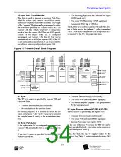
A1 & A2 Framing Bytes
F1 byte: Orderwire Channel
The frame keyword bytes are always regenerated in
the SXT6051 Transmitter regardless of the configura-
tion.
This byte is reserved for user purposes and can be used
as extra maintenance orderwire channel. Register 60H
specifies the F1 source to be either:
• The received byte (Regenerator mode) from the
Regenerator Section receiver. The received byte
from the transmit telecom bus (ADM mode)
The Regenerator Section Trace J0
This byte is inserted to repetitively transmit a Section
Access Identifier so that a section receiver can verify
its continued connection to the intended transmitter.
The 16 byte “expected” J0 string value needs to have
the correct CRC7 bits per G707 specifications. Regis-
ter 60H specifies the J0 source to be either:
• The dedicated 64 kbit/s serial interface (TDOW
input pin)
• Transmit Telecom bus (In ADM mode)
See note above.
• The received byte (Regenerator mode) from the
Regenerator Section receiver. The received byte
from the transmit telecom bus (ADM mode)
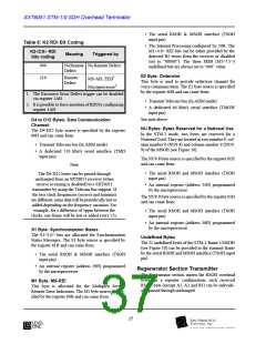
D1 to D3 Bytes: Data Communication Channel
This channel is used as a data channel by the network
management. Register 60H specifies the D1-D3
source to be either:
• The serial RSOH and MSOH interface (TSOH
input pin)
• The internal RAM (16 byte) programmed by the
microprocessor
• The received byte (Regenerator mode) from the
Regenerator Section receiver. The received byte
from the transmit telecom bus (ADM mode)
The RAM is accessed via registers 75H and 76H. Dur-
ing J0 RAM configuration the transmitted J0 byte
value is “01H.” Note that a complete 16-byte string
with CRC7 is required by the ITU for proper opera-
tion.
• A dedicated 192 kbit/s serial interface (TRD
input pin)
See note above
NU Bytes: Bytes Reserved for a National Use
In the STM-1 mode, four bytes are reserved for
National Use. They are located in row number 1, col-
umn numbers 8 (NU1-8) and 9 (NU1-9) and in row
number 2, column numbers 8 (NU2-8) and 9 (NU2-9)
of the MSOH (see Figure 10). Registers 61H and 30H
specify the source of these bytes. The possibilities are:
Compatibility of J0 with in-service equipment can be
provided by either writing a value into the transmit J0
RAM, or by setting register 3AH, to value ‘1’ (see reg-
ister 3AH).
B1 Bip-8 Byte
B1 byte is always regenerated in the SXT6051 trans-
mitter. This byte is used for the Regenerator Section
error monitoring function. It is the result of a BIP-8
calculation done on the previous scrambled frame, and
it is inserted into transmit RSOH before scrambling.
For testing purpose, it is possible to invert the B1
value, (register 30H). The B1 value can either be
inverted for a single frame (8 errors), or forever.
• The received byte (Regenerator mode) from the
Regenerator Section receiver.
• The serial RSOH and MSOH interface (TSOH
input pin)
• Internal registers (address 31H, 32H, 33H, 34H)
• Default value AAH (only for NU1-8 and NU1-9)
E1 Byte: Orderwire Channel
MD bytes: Media Dependent Bytes
This byte is used to provide an orderwire channel for
voice communication. Register 60H specifies the E1
source to be either:
In the STM-1 mode, the six media-dependent bytes are
located in raw number 2, column numbers 2 (MD2-2),
3 (MD2-3), and 5 (MD2-5) and in raw number 3, col-
umn numbers 2 (MD3-2), 3 (MD3-3), and 5 (MD3-5)
of the MSOH. Register 63H specifies the source of
these bytes. The possibilities are:
• The received byte (Regenerator mode) from the
Regenerator Section receiver. The received byte
from the transmit telecom bus (ADM mode)
• The received byte (Regenerator mode) from the
Regenerator Section receiver
• The dedicated 64 kbit/s serial interface (TROW
input pin)
See note above.
38
l

 LevelOne [ LEVEL ONE ]