SXT6051 STM-1/0 SDH Overhead Terminator
remote end. These REI errors are accumulated in the
REI counter registers 88H and 89H. The REI counter
can be selected as a bit counter or as a block counter
via register 80H.
Receive Higher Order path AIS (HptAIS)
The AIS generated after the HPOH receiver is labeled
HptAis. It can be inserted on the following conditions:
• SLM (C2 byte mismatches)
• TIM (J1 string mismatches)
G1<3:1> bits act as a Remote Detection Indication
(RDI). They, along with G1<0> (“spare” bit), are
accessible via register 85H. The contents of this regis-
ter is filtered over 3 or 5 frames configurable via reg-
ister 80H. An update to register 80H is indicated in
register A5H.
• Unequipped detection
The AIS can be disabled or forced via register 80H.
Re-Timing Function
The re-timing function block is used when the system
needs to synchronize the DTBDATA<7:0> output
with a local clock input. Re-timing can be disabled via
register 51H.
An RDI is reported to the far-end upon detection of an
SLM (C2 Mismatch) or an “unequipped” alarm. The
dependency of RDI on either of these conditions is
configurable via 81H. This will ensure compatibility
of the new equipment with an installed equipment
base. (See Table 5).
Two external signals are required to align the payload:
• DRETFRI, an 8 KHz input signal indicating the
position of the J0 byte. This input is always
needed.
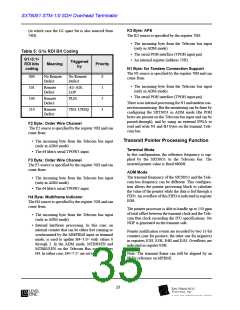
K3 Byte
This byte is allocated for the VC-3 and VC-4 Auto-
matic Protection Switching (APS). A change in K3
byte for three consecutive frames is indicated in regis-
ter A4H and allows the updating of register 84H.
• DRETCLK, a 19.44 MHz input signal for a
STM-1 or a 6.48 MHz input signal for STM-0.
This is the “local” clock.
The DRETFRMI is generated externally by DRET-
CLK. The re-timing function recalculates the new
pointer and inserts the new value to the payload VC-3
and VC-4.
N1 Byte
There is no internal processing for the tandem connec-
tion byte. This is because in an ADM, the virtual con-
tainer VC-3 or VC-4 is de-multiplexed to VC12 to
extract and insert the VC-12 traffic. A new B3 needs
to be generated and the tandem connection is broken.
After the re-timing block, the signal is sent to the Tele-
com Bus. The Telecom Bus is described in the Timing
Specification part of this document.
N1 is accessible at the RPOH output and can be used
in the detection of an “unequipped” VC (see register
81H).
Note that when the receive re-timing function is
enabled, the AU pointer and the A1/A2 frame word are
still present on the Telecom Bus.
F2 and F3 Bytes
These two 64 Kbit/s channels are reserved for the user.
They can be used as an extra maintenance orderwire
access. The data is serially accessible via the RPOW1
pin for F2 and RPOW2 for F3. The 64 KHz clock and
8KHz synchronization are provided on pins RPOWC
and RPOWBYC. In an ADM configuration with no
receive timing, these bytes can be passed through to
the transmit side.
Transmitter Default Operation
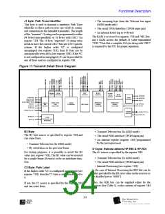
Higher Order Path Transmitter
The HPT transmitter receives its input signal from the
MTBDATA<7:0> Telecom Bus Interface input. It
inserts the Higher Order Path Overhead and synchro-
nizes the VC-3 or the VC-4. The Telecom Bus inter-
face is configured via registers 50H and 71H.
H4 Processing and Multi-Frame Recovery
The multi-frame recovery state machine requires two
consecutive frames with the correct H4 adjacent pat-
tern to synchronize. The Loss of Multiframe (LOM),
indicated in register A5H, is declared after two multi-
frames. The LOM indication forces the DTBH4EN
output on the Telecom Bus Low.
All HPOH bytes can be sourced from the serial TPOH
input, received bytes (ADM mode only), microproces-
sor registers or internal processing. An AIS signal can
be forced on the incoming payload data via register
71H. The parity on the Telecom bus is checked (three
parity errors per frame) and indicated in register E0H.
33

 LevelOne [ LEVEL ONE ]