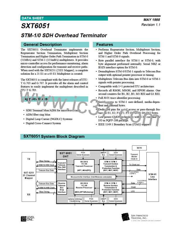
SXT6051 STM-1/0 SDH Overhead Terminator
K1 and K2 Bytes: Automatic Protection
Channel
both the E1 and F1 bytes and are provided at pins
ROWC and ROWBYC.
These bits are assigned for the APS signaling. A
change in K1 byte for three consecutive frames is indi-
cated in register A1H and allows the updating of reg-
ister 00H. A change in K2 byte for three consecutive
frames is indicated in register A1H and allows the
updating of register 01H.
D4 to D12 Bytes: Data Channel
This 576 Kbit/s channel is used as a data channel by
the network management. The data is accessible via
pin RMD and the clock is provided by RMDC.
Receive Multiplexer Section AIS (MS-AIS)
The AIS generated after the multiplexer section is
labeled MstAis. It can be inserted on the following
conditions:
MS-RDI via K2 Byte
The Multiplex Section Remote Defect Indication (MS-
RDI) is used to tell the transmit end that the received
end has detected an incoming section defect or is
receiving MS-AIS. An MS-RDI is detected when the
three received K2<2:0> bits have a value of “110” for
three consecutive frames. MS-RDI detector status
changes are indicated in register A1H.
• MS-AIS detection in K2
• EED detection
The AIS insertion can disabled or forced via register
20H. The EED dependency can be disabled via regis-
ter 20H (ITU specification). MstAis insertion is indi-
cated in register D0H.
MS-AIS via K2 Byte
The Multiplex Section AIS is detected when the three
received K2<2:0> bits have a value of “111” for three
consecutive frames. MS-AIS detector status changes
are indicated in register A1H.
Multiplexer Section Protection (MSP)
Block
Master 1-for-1 Protection Configuration
The MSP block receives the data coming from the
MST block and from the slave receiver via the DMSP-
PDATA<7:0> inputs (MSP bus). K1 and K2 from the
MSP bus are de-multiplexed and accessible in regis-
ters 22H and 23H. The Signal Degrade (SD) and the
Signal Fail (SF) indications from the slave are input to
the Master at DMSPPSD & DMSPPSF respectively
and are accessible in register C3H.
MS-REI via M1 Byte
This byte is allocated for the Remote Error Indication.
Remote BIP errors are accumulated in a 13-bit
counter, accessible via registers 0AH and 09H.
Remote block errors are accumulated in an 18-bit
counter, accessible via registers 0DH, 0CH and 0BH.
S1 Byte: Synchronization Status
S1<3:0> bits are allocated for Synchronization Status
Messages. A change in S1 byte for three consecutive
frames is indicated in register A2H and allows the
updating of register 02H.
Changes in register 22H, 23H, DMSPPSD or
DMSPPSF are indicated in register A3H.
Having access to the K1 and K2, SD and SF informa-
tion for both the master and the slave SXT6051, the
microprocessor can select the appropriate working
channel. The selection is done by setting the protection
switch via register 21H. The effective switch position
is accessible on register D0H.
National Used Bytes
The “National Use” bytes are only accessible in the
STM-1 case. There are two MSOH “National Use”
bytes. These bytes can be read via registers 07H and
08H.
Undefined Bytes
K1/K2 filtering and SF detection are done on chip. The
SD detection is done by the microprocessor using a
user defined criteria.
The “Undefined Bytes” are only accessible in the
STM-1 case. There are 26 bytes only accessible via the
RSOH serial output.
Slave 1-for-1 Protection Configuration
This block is just an interface between the data
received from the MST block and the MSP interface
with the Master. All switching is done in the master-
configured SXT6051.
E2 Byte: Orderwire Channel
This 64 Kbit/s channel is used to provide orderwire
channel for voice communication. The data is accessi-
ble serially via RMOW. The 64 KHz clock and the 8
KHz byte synchronization signals are used to receive
31

 LevelOne [ LEVEL ONE ]