LTC4270/LTC4271
APPLICATIONS INFORMATION
3.3V
0.1μF
V
XIO0
XIO1
0.22μF
100V
DD33
GP0
GP1
S1B
S1B
NO ISOLATION
REQUIRED ON
I C INTERFACE
CPD
CPA
PORTn
OUTn
MID
2
100Ω
–54V
100Ωt
t
t
RESET
MSD
AUTO
INT
GATEn
3.3V
3.3V
0.25Ω
100Ω
100Ω
–54V
SENSEn
CND
DPD
CNA
DPA
T1
T2
LTC4271
LTC4270
SCL
SDAIN
SDAOUT
0.22μF
100V
S1B
S1B
100Ω
100Ωt
PORT1
OUT1
–54V
100Ω
AD0
AD1
AD2
AD3
AD6
100Ω
GATE1
DND
DNA
0.25Ω
SENSE1
VSSK AGND
–54V
V
DGND
CAP1
CAP2
EE
1μF
2nF, 2kV
0.1μF
+
>47μF
SYSTEM
1μF
BULK CAP
–54V
–54V
42701 F16
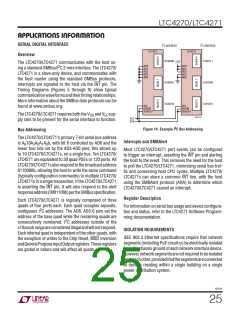
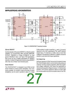
Figure 15. LTC4270/LTC4271 Proprietary Isolation
External MOSFET
0.25Ω resistor. In order to meet the I and I accuracy
CUT LIM
required by the IEEE specification, the sense resistors
should have 1% tolerance or better, and no more than
200ppm/°Ctemperaturecoefficient.Inaddition,thesense
resistors must meet strict layout guidelines.
CarefulselectionofthepowerMOSFETiscriticaltosystem
reliability. LTC recommends either Fairchild IRFM120A,
FDT3612, FDMC3612 or Philips PHT6NQ10T for their
proven reliability in Type 1 and Type 2 PSE applications.
SOA curves are not a reliable specification for MOSFET
selection.ContactLTCApplicationsbeforeusingaMOSFET
other than one of these recommended parts.
Port Output Cap
Each port requires a 0.22ꢀF cap across its outputs to keep
the LTC4270 stable while in current limit during startup or
overload. Common ceramic capacitors often have signifi-
cant voltage coefficients; this means the capacitance is
reduced as the applied voltage increases. To minimize this
problem, X7R ceramic capacitors rated for at least 100V
are recommended and must be located close to the PSE.
Sense Resistor
The LTC4270/LTC4271 is designed to use 0.25Ω current
sense resistors to reduce power dissipation. Four com-
monly available 1Ω resistors (sized according to power
dissipation) can be used in parallel in place of a single
42701f
27

 Linear [ Linear ]