LTC4270/LTC4271
APPLICATIONS INFORMATION
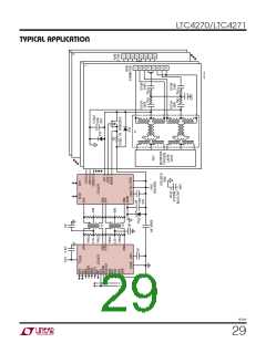
SERIAL DIGITAL INTERFACE
2
2
I C ADDRESS
I C ADDRESS
LTC4271
LTC4271
Overview
0100000
0100001
0100010
0100111
0101000
0101001
3.3V
The LTC4270/LTC4271 communicates with the host us-
ing a standard SMBus/I C 2-wire interface. The LTC4270/
AD0
AD1
AD2
AD3
AD6
AD0
AD1
AD2
AD3
AD6
2
LTC4271 is a slave-only device, and communicates with
the host master using the standard SMBus protocols.
Interrupts are signaled to the host via the INT pin. The
Timing Diagrams (Figures 5 through 9) show typical
communicationwaveformsandtheirtimingrelationships.
More information about the SMBus data protocols can be
found at www.smbus.org.
SCL
SCL
SDAIN
SDAIN
SDAOUT
SDAOUT
The LTC4270/LTC4271 requires both the V and V sup-
DD
EE
42701 F15
SCL
SDA
ply rails to be present for the serial interface to function.
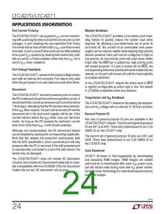
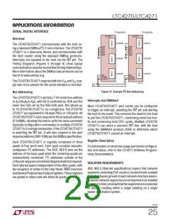
Figure 14. Example I2C Bus Addressing
Bus Addressing
The LTC4270/LTC4271’s primary 7-bit serial bus address
Interrupts and SMBAlert
is A 10A A A A b, with bit 6 controlled by AD6 and the
6
3 2 1 0
lower four bits set by the AD3-AD0 pins; this allows up
to 10 LTC4270/LTC4271s, on a single bus. Ten LTC4270/
LTC4271 are equivalent to 30 quad PSEs or 120 ports. All
LTC4270/LTC4271salsorespondtothebroadcastaddress
0110000b, allowing the host to write the same command
(typically configuration commands) to multiple LTC4270/
LTC4271s in a single transaction. If the LTC4270/LTC4271
is asserting the INT pin, it will also respond to the alert
responseaddress(0001100b)pertheSMBusspecification.
Most LTC4270/LTC4271 port events can be configured
to trigger an interrupt, asserting the INT pin and alerting
the host to the event. This removes the need for the host
to poll the LTC4270/LTC4271, minimizing serial bus traf-
fic and conserving host CPU cycles. Multiple LTC4270/
LTC4271s can share a common INT line, with the host
using the SMBAlert protocol (ARA) to determine which
LTC4270/LTC4271 caused an interrupt.
Register Description
Each LTC4270/LTC4271 is logically composed of three
quads of four ports each. Each quad occupies separate,
For information on serial bus usage and device configura-
tion and status, refer to the LTC4271 Software Program-
ming documentation.
2
contiguous I C addresses. The AD6, AD3-0 pins set the
address of the base quad while the remaining quads are
2
consecutively numbered. I C addresses outside of the
x10xxxxbrangeareconsideredillegalandwillnotrespond.
Each internal quad is independent of the other quads, with
the exception of writes to the Chip Reset, MSD Inversion
andGeneralPurposeInputOutputregisters.Theseregisters
are global in nature and will affect all quads.
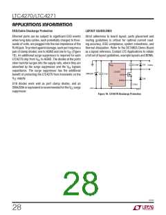
ISOLATION REQUIREMENTS
IEEE 802.3 Ethernet specifications require that network
segments (including PoE circuitry) be electrically isolated
from the chassis ground of each network interface device.
However,networksegmentsarenotrequiredtobeisolated
fromeachother,providedthatthesegmentsareconnected
to devices residing within a single building on a single
power distribution system.
42701f
25

 Linear [ Linear ]