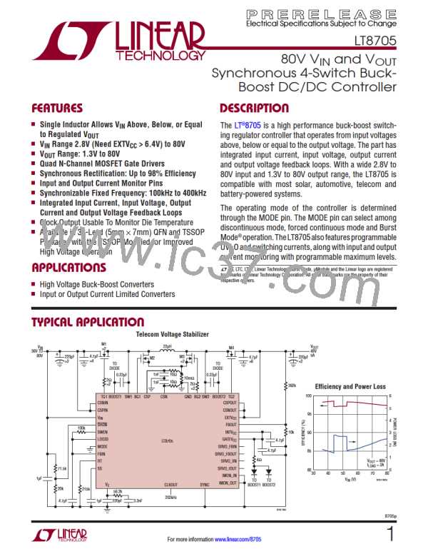
LT8705
APPLICATIONS INFORMATION
The maximum current drawn through the INTV LDO
INTV Regulators and EXTV Connection
CC
CC
CC
occurs under the following conditions:
The LT8705 features two PNP LDOs (low dropout regu-
lators) that regulate the 6.35V (typical) INTV pin from
1. Large (capacitive) MOSFETs are being driven at high
frequencies.
CC
either the V or EXTV supply pin. INTV powers the
IN
CC
CC
MOSFET gate drivers via the required GATEV connec-
CC
2. V and/or V
is high, thus requiring more charge to
IN
OUT
tion and also powers the LDO33 pin regulator and much
turn the MOSFET gates on and off.
of the LT8705’s internal control circuitry. The INTV
LDO selection is determined automatically by the EXTV
CC
CC
3. The LDO33 pin output current is high.
pin voltage. When EXTV is lower than 6.22V (typical),
CC
4. In some applications, LDO current draw is maximum
when the part is operating in the buck-boost region
INTV is regulated from the V LDO. After EXTV rises
CC
IN
CC
above 6.4V (typical), INTV is regulated by the EXTV
CC
CC
where V is close to V
since all four MOSFETs are
IN
OUT
LDO instead.
switching.
Overcurrent protection circuitry typically limits the
maximum current draw from either LDO to 127mA. When
Tocheckforoverheatingfindtheoperatingconditionsthat
consume the most power in the LT8705 (P ). This
will often be under the same conditions just listed that
maximize LDO current. Under these conditions monitor
theCLKOUTpindutycycletomeasuretheapproximatedie
temperature.SeetheJunctionTemperatureMeasurement
section for more information.
LT8705
GATEV and INTV are below 4.65V, during start-up or
CC
CC
during an overload condition, the typical current limit is
reduced to 42mA. The INTV pin must be bypassed to
CC
ground with a minimum 4.7μF ceramic capacitor placed
as close as possible to the INTV and GND pins. An ad-
CC
ditional ceramic capacitor should be placed as close as
Powering INTV from V /EXTV can also provide
CC
OUT
CC
possible to the GATEV and GND pins to provide good
CC
enough gate drive when V drops as low as 2.8V. This
IN
bypassing to supply the high transient current required by
allows the part to operate with a reduced input voltage
the MOSFET gate drivers. 1μF to 4.7μF is recommended.
after the output gets into regulation.
Power dissipated in the INTV LDOs must be minimized
CC
The following list summarizes the three possible connec-
to improve efficiency and prevent overheating of the
tions for EXTV :
CC
LT8705. Since LDO power dissipation is proportional to
the input voltage and V can be as high as 80V in some
1. EXTV left open (or grounded). This will cause INTV
IN
CC
CC
applications, the EXTV pin is available to regulate IN-
to be powered from V through the internal 6.35V
CC
IN
TV from a lower input voltage. The EXTV pin is con-
regulator at the cost of a small efficiency penalty.
CC
CC
nected to V
in many applications since V
is often
OUT
OUT
2. EXTV connected directly to V
(V
> 6.4V). This
CC
OUT OUT
regulated to a much lower voltage than the maximum V .
IN
is the normal connection for the regulator and usually
provides the highest efficiency.
During start-up, power for the MOSFET drivers, control
circuits and the LDO33 pin is derived from V until V
/
IN
OUT
3. EXTV connected to an external supply. If an external
EXTV rises above 6.4V, after which the power is derived
CC
CC
OUT
supply is available greater than 6.4V (typical) it may be
from V /EXTV . This works well, for example, in a
CC
used to power EXTV .
case where V
is regulated to 12V and the maximum
CC
OUT
V
voltage is 40V. EXTV can be floated or grounded
IN
CC
when not in use or can also be connected to an external
power supply if available.
8705p
32
For more information www.linear.com/8705

 Linear [ Linear ]