LT8705
APPLICATIONS INFORMATION
output ripple voltage. The steady-state output ripple due
to charging and discharging the bulk output capacitance
is given by the following equations:
polymer,aluminumelectrolyticandceramiccapacitorsare
all available in surface mount packages. Capacitors with
low ESR and high ripple current ratings, such as OS-CON
and POSCAP are also available.
IOUT • V
– V
IN
(
)
V for VOUT > V
OUT
∆V BOOST,CAP
≅
IN
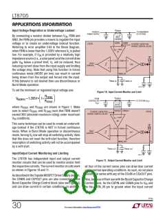
Ceramic capacitors should be placed near the regulator
input and output to suppress high frequency switching
spikes.Aceramiccapacitor,ofatleast1µFatthemaximum
(
)
COUT •V •f
IN
VOUT
V
OUT • 1–
V operating voltage, should also be placed from V to
IN
IN
V
IN
GND as close to the LT8705 pins as possible. Due to their
excellent low ESR characteristics ceramic capacitors can
significantly reduce input ripple voltage and help reduce
power loss in the higher ESR bulk capacitors. X5R or X7R
dielectrics are preferred, as these materials retain their
capacitance over wide voltage and temperature ranges.
Many ceramic capacitors, particularly 0805 or 0603 case
sizes, have greatly reduced capacitance at the desired
operating voltage.
∆V
≅
V for VOUT < V
IN
(BUCK,CAP)
8•L•f2 •COUT
Themaximumoutputrippleduetothevoltagedropacross
the ESR is approximately:
VOUT(MAX) •I
∆V
≅
OUT(MAX) •ESR
(BOOST,ESR)
V
IN(MIN)
As with C , multiple capacitors placed in parallel may
IN
be needed to meet the ESR and RMS current handling
InputCapacitance:Discontinuousinputcurrentishighest
requirements.
inthebuckregionduetotheM1switchtogglingonandoff.
Make sure that the C capacitor network has low enough
IN
Schottky Diode (D1, D2) Selection
ESR and is sized to handle the maximum RMS current.
For buck operation, the input RMS current is given by:
The Schottky diodes, D1 and D2, shown in Figure 1, con-
duct during the dead time between the conduction of the
power MOSFET switches. They are intended to prevent
the body diodes of synchronous switches M2 and M4
from turning on and storing charge. For example, D2
significantly reduces reverse-recovery current between
switchM4turn-offandswitchM3turn-on,whichimproves
converterefficiency,reducesswitchM3powerdissipation
and reduces noise in the inductor current sense resistor
VOUT
V
IN
VOUT
IRMS ≅ IOUT(MAX)
•
•
–1
V
IN
This formula has a maximum at V = 2V , where
IN
OUT
I
= I
/2. This simple worst-case condition
RMS
OUT(MAX)
is commonly used for design because even significant
deviations do not offer much relief.
The maximum input ripple due to the voltage drop across
the ESR is approximately:
(R
) when M3 turns on. In order for the diode to be
SENSE
effective, the inductance between it and the synchronous
switch must be as small as possible, mandating that these
components be placed adjacently.
VIN(MAX) •I
OUT(MAX) •ESR
VOUT(MIN)
∆V
≅
(BUCK,ESR)
For applications with high input or output voltages (typi-
cally>40V)avoidSchottkydiodeswithexcessivereverse-
leakage currents particularly at high temperatures. Some
Output Capacitance: The output capacitance (C ) is
OUT
necessary to reduce the output voltage ripple caused by
discontinuities and ripple in the output and load currents.
The effects of ESR and the bulk capacitance must be
considered when choosing the right capacitor for a given
ultralowV diodeswilltradeoffincreasedhightemperature
F
leakage current for reduced forward voltage. Diode D1
8705p
28
For more information www.linear.com/8705

 Linear [ Linear ]