LT8705
OPERATION
When V
is much higher than V the duty cycle of
age current is delivered to the output. During soft-start,
when the SS pin is below 1.6V, the part will be forced
into discontinuous mode to prevent pulling current from
the output to the input. After SS rises above 1.6V, forced
continuous mode will be enabled.
OUT
IN
switch M3 will increase, causing the M3 switch off-time
to decrease. The M3 switch off-time should be kept above
245ns (typical, see Electrical Characteristics) to maintain
steady-state operation, avoid duty cycle jitter, increased
output ripple and reduction in maximum output current.
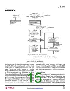
Voltage Regulation Loops
Light Load Current Operation (MODE Pin)
The LT8705 provides two constant-voltage regulation
loops, one for output voltage and one for input voltage.
Under light current load conditions, the LT8705 can be set
tooperateindiscontinuousmode,forcedcontinuousmode,
orBurstModeoperation.Toselectforcedcontinuousmode,
tie the MODE pin to a voltage below 0.4V (i.e., ground). To
select discontinuous mode, tie MODE to a voltage above
2.3V (i.e., LDO33). To select Burst Mode operation, float
the MODE pin or tie it between 1.0V and 1.7V.
A resistor divider between V , FBOUT and GND senses
OUT
the output voltage. As with traditional voltage regulators,
when FBOUT rises near or above the reference voltage of
EA4 (1.207V typical, see Block Diagram), the V voltage
C
is reduced to command the amount of current that keeps
V
OUT
regulated to the desired voltage.
Discontinuous Mode: When the LT8705 is in discontinu-
ous mode, synchronous switch M4 is held off whenever
reversecurrentintheinductorisdetected.Thisistoprevent
current draw from the output and/or feeding current to the
input supply. Under very light loads, the current compara-
tor may also remain tripped for several cycles and force
switches M1 and M3 to stay off for the same number of
cycles (i.e., skipping pulses). Synchronous switch M2 will
remain on during the skipped cycles, but since switch M4
is off, the inductor current will not reverse.
The input voltage can also be sensed by connecting a
resistor divider between V , FBIN and GND. When the
IN
FBIN voltage falls near or below the reference voltage of
EA3 (1.205V typical, see Block Diagram), the V voltage is
C
reduced to also reduce the input current. For applications
withahighinputsourceimpedance(i.e.,asolarpanel),the
inputvoltageregulationloopcanpreventtheinputvoltage
frombecomingtoolowunderhighoutputloadconditions.
Forapplicationswithalowerinputsourceimpedance(i.e.,
batteries and voltage supplies), the FBIN pin can be used
to stop switching activity when the input power supply
voltage gets too low for proper system operation. See the
Applications Information section for more information
about setting up the voltage regulation loops.
Burst Mode Operation: Burst Mode operation sets a
V level, with about 25mV of hysteresis, below which
C
switching activity is inhibited and above which switching
activity is re-enabled. A typical example is when, at light
outputcurrents,V
risesandforcestheV pinbelowthe
C
OUT
Current Monitoring and Regulation
threshold that temporarily inhibits switching. After V
OUT
dropsslightlyandV rises~25mVtheswitchingisresumed,
C
The LT8705 provides two constant-current regulation
loops, one for input current and one for output current. A
sensing resistor close to the input capacitor, sensed by
CSPIN and CSNIN, monitors the input current. A current,
initially in the buck-boost region. Burst Mode operation
canincreaseefficiencyatlightloadcurrentsbyeliminating
unnecessary switching activity and related power losses.
Burst Mode operation handles reverse-current detection
similar to discontinuous mode. The M4 switch is turned
off when reverse current is detected.
linearlyproportionaltothesensevoltage(V
-V
),
CSPIN CSNIN
is forced out of the IMON_IN pin and into an external re-
sistor. The resulting voltage V is therefore linearly
IMON_IN
proportional to the input current. Similarly, a sensing
resistor close to the output capacitor, and sensed by
CSPOUT and CSNOUT will monitor the output current and
IMON_OUT
to the output current.
Forced Continuous Mode: The forced continuous mode
allows the inductor current to reverse directions without
any switches being forced “off” to prevent this from hap-
pening. At very light load currents the inductor current
will swing positive and negative as the appropriate aver-
generate a voltage V
that is linearly proportional
8705p
18
For more information www.linear.com/8705

 Linear [ Linear ]