LT8705
APPLICATIONS INFORMATION
Referring to the Maximum Inductor Current Sense Volt-
age graph in the Typical Performance Characteristics
After the maximum ripple current is known, the maximum
allowed R
follows:
in the boost region can be calculated as
SENSE
section, the maximum R
voltage at 67% duty cycle
SENSE
is ≅93mV, or:
RSENSE(MAX,BOOST)
=
V
≅93mV
RSENSE(MAX,BOOST, MAX)
2•VRSENSE(MAX,BOOST,MAX) •V
IN(MIN)
Ω
for V = 12V, V
= 36V.
IN
OUT
2•IOUT(MAX,BOOST) •VOUT(MIN) + ∆I
•V
IN(MIN)
(
) (
)
L(MAX,BOOST)
Next, the inductor ripple current in the boost region must
be determined. If the main inductor L is not known, the
where V
is the maximum inductor
RSENSE(MAX,BOOST,MAX)
currentsensevoltageasdiscussedintheprevioussection.
maximum ripple current ∆I
can be estimated
L(MAX,BOOST)
by choosing ∆I
to be 30% to 50% of the
L(MAX,BOOST)
Using values from the previous examples:
maximum inductor current in the boost region as follows:
2•93mV •12
2•2A •36V + 3A •12V
) (
RSENSE(MAX,BOOST)
=
= 12.4mΩ
VOUT(MAX) •I
OUT(MAX,BOOST) A
(
)
∆IL(MAX,BOOST)
≅
100%
V
•
–0.5
IN(MIN)
%Ripple
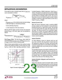
BuckRegion:Inthebuckregion,themaximumoutputcur-
rent capability is the least when operating at the minimum
duty cycle. This is because the slope compensation ramp
where:
increases the maximum R
voltage with increasing
SENSE
I
is the maximum output load current
OUT(MAX,BOOST)
duty cycle. The minimum duty cycle for buck operation
can be calculated using:
required in the boost region
%Ripple is 30% to 50%
DC
≅ t
• f • 100%
ON(M2,MIN)
(MIN,M2,BUCK)
For example, using V
OUT(MAX,BOOST)
= 36V, V
= 12V,
IN(MIN)
OUT(MAX)
where t
is 260ns (typical value, see Electrical
ON(M2,MIN)
Characteristics)
I
=2Aand%Ripple=40%wecanestimate:
36V •2A
∆IL(MAX,BOOST)
≅
= 3A
Before calculating the maximum R
however, the inductor ripple current must be determined.
If the main inductor L is not known, the ripple current
resistance,
100%
40%
SENSE
12V •
–0.5
Otherwise, if the inductor value is already known then
∆I can be more accurately calculated as
∆I
canbeestimatedbychoosing ∆I
L(MIN,BUCK)
L(MIN,BUCK)
L(MAX,BOOST)
to be 10% of the maximum inductor current in the buck
follows:
region as follows:
DC
(MAX,M3,BOOST)
I
OUT(MAX,BUCK) A
•V
∆IL(MIN,BUCK)
≅
IN(MIN)
100%
f•L
100%
10%
–0.5
∆IL(MAX,BOOST)
=
A
where:
DC
where:
is the maximum duty cycle percent-
I
is the maximum output load current
(MAX,M3,BOOST)
age in the boost region as calculated previously.
OUT(MAX,BUCK)
required in the buck region.
f is the switching frequency
L is the inductance of the main inductor
8705p
22
For more information www.linear.com/8705

 Linear [ Linear ]