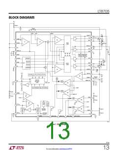
LT8705
OPERATION
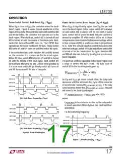
Power Switch Control: Buck-Boost (V ≅ V
)
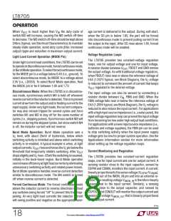
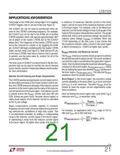
Power Switch Control: Boost Region (V << V
)
OUT
IN
OUT
IN
When V is close to V , the controller enters the buck-
When V
is significantly higher than V , the part will
IN
OUT
OUT IN
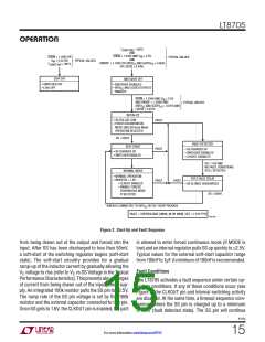
boost region. Figure 6 shows typical waveforms in this
region.Everycycle,ifthecontrollerstartswithswitchesM2
and M4 turned on, the controller first operates as if in the
buck region. When A8 trips, switch M2 is turned off and
M1 is turned on until the middle of the clock cycle. Next,
switch M4 turns off and M3 turns on. The LT8705 then
operates as if in boost mode until A9 trips. Finally switch
M3 turns off and M4 turns on until the end of the cycle.
run in the boost region. In this region switch M1 is always
on and switch M2 is always off. At the start of every
cycle, switch M3 is turned on first. Inductor current is
sensed by amplifier A5 while switch M3 is on. A slope
compensation ramp is added to the sensed voltage which
is then compared (A9) to a reference that is proportional
to V . After the sensed inductor current rises above the
C
reference voltage, switch M3 is turned off and switch M4
is turned on for the remainder of the cycle. Switches M3
and M4 will alternate, behaving like a typical synchronous
boost regulator.
If the controller starts with switches M1 and M3 turned
on, the controller first operates as if in the boost region.
When A9 trips, switch M3 is turned off and M4 is turned
on until the middle of the clock cycle. Next, switch M1
turns off and M2 turns on. The LT8705 then operates as
if in buck mode until A8 trips. Finally switch M2 turns off
and M1 turns on until the end of the cycle.
The part will continue operating in the boost region over
a range of switch M3 duty cycles. The duty cycle of
switch M3 in the boost region is given by:
V
IN
DC(M3,BOOST) = 1–
•100%
VOUT
CLOCK
SWITCH M1
As V and V
get closer to each other, the duty cycle
IN
OUT
decreases until the minimum duty cycle of the converter
in boost mode reaches DC . If the duty
(ABSMIN,M3,BOOST)
will move to the buck-boost region:
SWITCH M2
SWITCH M3
SWITCH M4
(ABSMIN,M3,BOOST)
cycle becomes lower than DC
the part
I
L
DC ≅ t
• f • 100%
ON(M3,MIN)
(ABSMIN,M3,BOOST)
8705 F06a
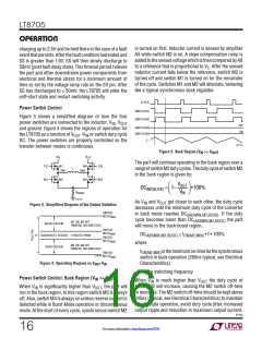
(6a) Buck-Boost Region (VIN ≥ VOUT
)
where:
t
istheminimumon-timeforthemainswitch
ON(M3,MIN)
CLOCK
in boost operation (265ns typical, see Electrical Char-
acteristics)
SWITCH M1
SWITCH M2
f is the switching frequency
SWITCH M3
SWITCH M4
CLOCK
ON
SWITCH M1
OFF
I
SWITCH M2
L
8705 F06b
SWITCH M3
SWITCH M4
(6b) Buck-Boost Region (VIN ≤ VOUT
)
Figure 6. Buck-Boost Region
I
L
8705 F07
Figure 7. Boost Region (VIN << VOUT
)
8705p
17
For more information www.linear.com/8705

 Linear [ Linear ]